UM2206 Rev 3 21/55
UM2206 Hardware layout and configuration
54
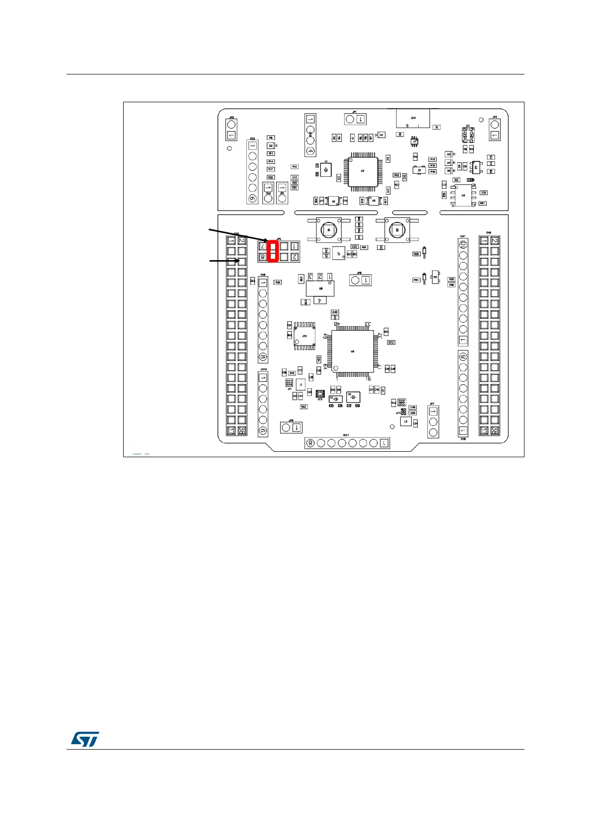
Figure 12. JP5[5-6]: E5V power source
5V_USB_CHARGER is the DC power charger connected to USB ST-LINK (CN1). To select
the 5V_USB_CHARGER power source on silkscreen of JP5, the jumper of JP5 should be
on pins 7 and 8. In this case, if the STM32 Nucleo-64-P board is powered by an external
USB charger the debug is not available. If the PC is connected instead of the charger, the
limitation is no more effective, in this case the PC could be damaged.
5V_USB_CHG configuration: jumper JP5[7-8] should be connected as showed in Figure 13.
E5V: CN5 pin 6
PWR connector:
JP5 [5-6] ON
 Loading...