Hardware overview UM1681
10/23 UM1681 Rev 3
2.4 Programming and debug
The microcontroller in the discovery board can be programmed and debugged using two
methods
(b)
:
Standard JTAG connector (male 2 x 7 100 mil - 90°)
USB port with integrated debugger.
A further configuration in addition to the previous configurations allows configuring the board
as a standalone PLS adapter; in this case, the JTAG connector has to be connected to the
target board adding a passive male-female 2 x 7 pin adaptor.
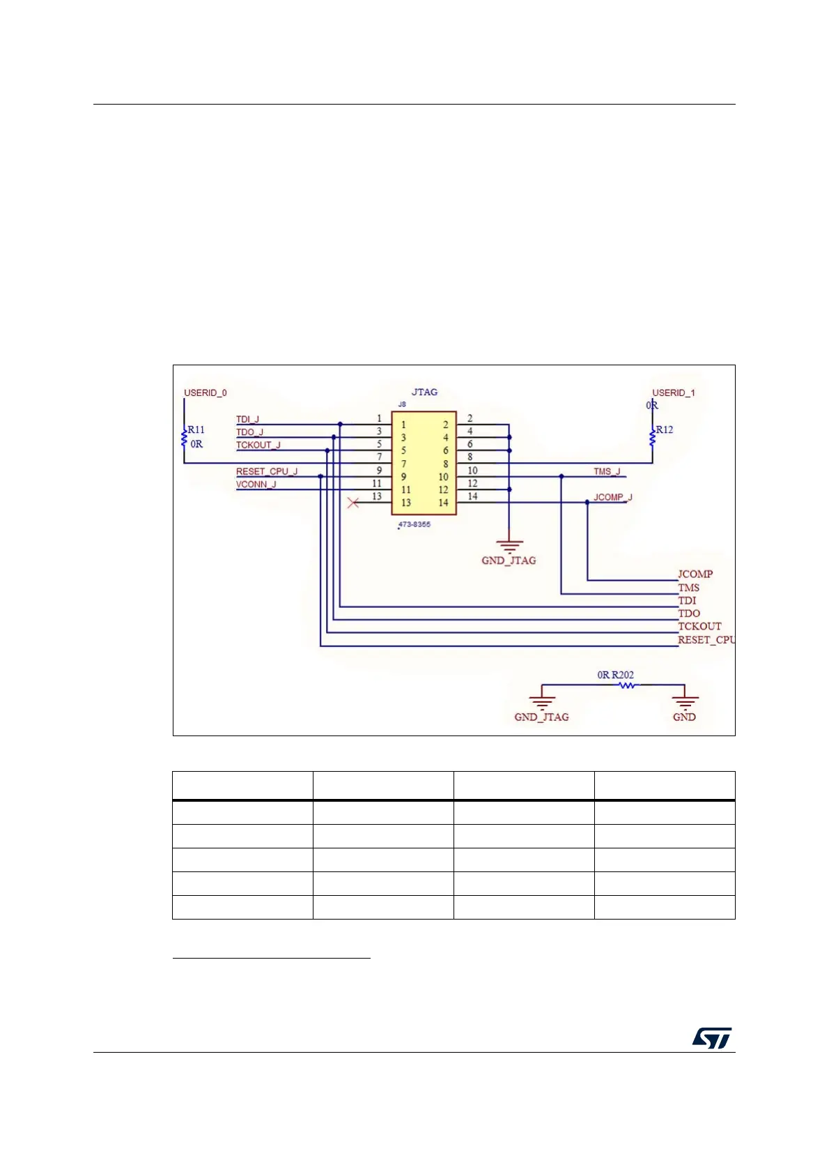
2.4.1 JTAG connector
Figure 7. JTAG connectors (Schematic and PCB)
b. A single configuration can be enabled at a time. The jumper setting to enable the configuration is
described in the Section 2.4.4: HW configuration.
Table 2. JTAG connector (pin out)
Pin num. Name Pin num. Name
1 TDI 2 GND
3 TDO 4 GND
5 TCK 6 GND
7 EVTI 8 NC
9 RESET 10 TMS