UM1681 Rev 3 11/23
UM1681 Hardware overview
22
2.4.2 USB with integrated debugger from PLS (default configuration)
The integrated debugger, based on the device FTDI2232H and UDE PLS software, allows
the user to build, run and debug the software applications. The SPC560D-DIS discovery kit
includes a full-featured, perpetual code-limited (128 Kbytes) PLS software license; the
debugger serial number is reported on a label applied on bottom side of the board.
To download the debugger software and to activate license go to the PLS website.
The integrated debugger is accessible via ST's free integrated development environment,
SPC5Studio (www.st.com/spc5studio
).
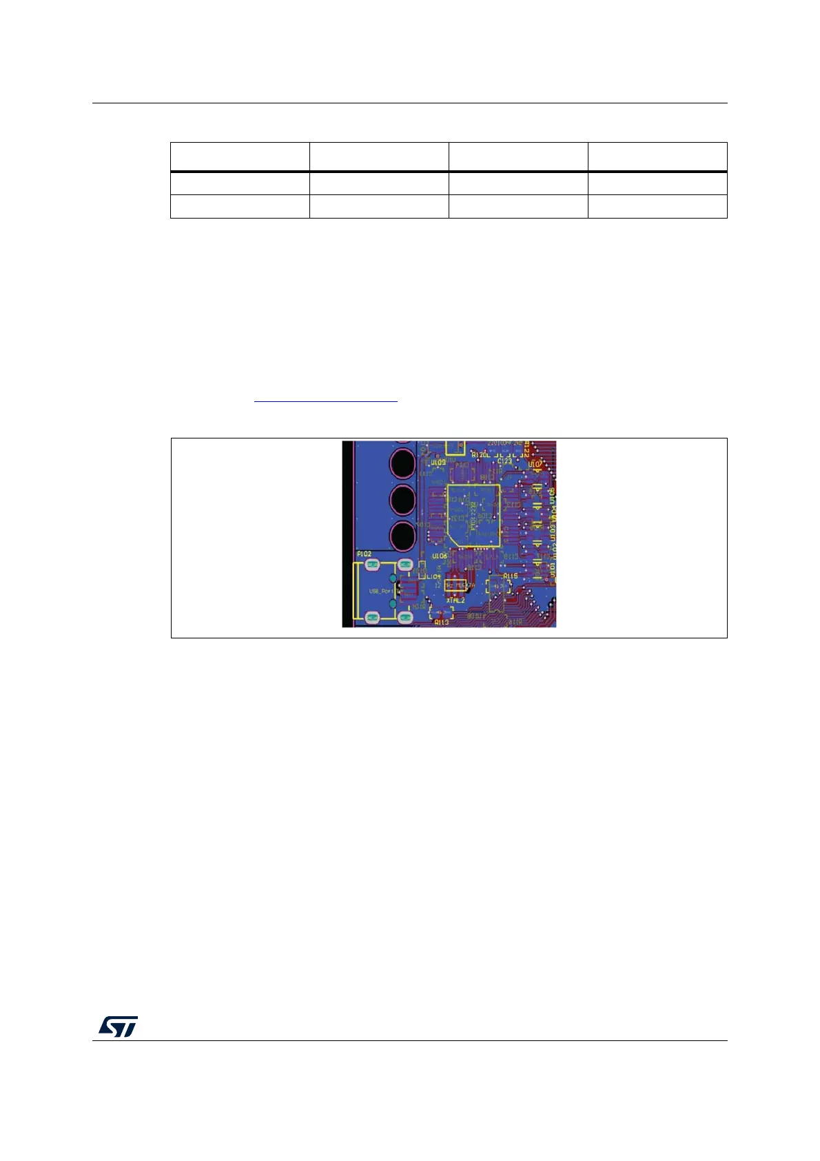
Figure 8. USB connector with integrated debugger from PLS
2.4.3 Board configured as PLS adapter
The discovery board can be configured to work as standalone PLS adapter, configuring
jumpers as described below (see Table 3: Programming and debug - Jumper setting). The
board serial number is reported in a label on the board.
Using such configuration the JTAG connector is connected to the JTAG application board; a
passive adapter can be added to converter from male to female the 2 x 7 JTAG port
soldered on the board. The 3.3 V or 5 V compatibility is achieved by using level shifters
array.
2.4.4 HW configuration
In order to enable one of the previous described functionalities, the board has to be properly
set. The USB integrated debugger is the default configuration.
Table 3 shows how to configure the jumpers also to enable the board as PLS adapter.
11 VDDE7 12 GND
13 RDY 14 JCOMP
Table 2. JTAG connector (pin out) (continued)
Pin num. Name Pin num. Name