Hardware overview UM1681
8/23 UM1681 Rev 3
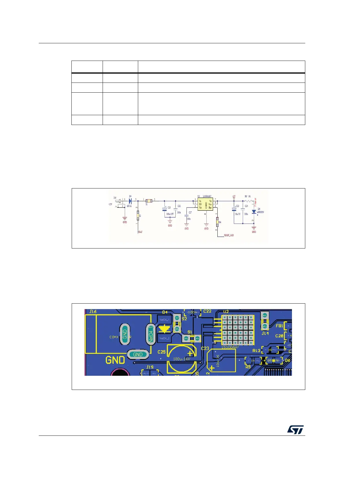
The jumper S1 can be used as switch to turn on and off the board.
A linear regulator is used to generate +5 V
DC
needed for the microcontroller. D4 (green
LED) is connected to voltage regulator output for revealing 5 V presence.
Figure 3. +5 V supply section
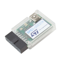
2.1.2 Supply from USB port
The board can be fed using the +5V from the USB cable. To enable this function both
jumpers J19 and J20 have to be closed and the PSU plug can be removed, together with S1
and S2 jumpers.
Figure 4. Power supply section
Table 1. + 12 V Supply configuration, S1 and S2 jumpers configuration
S1 S2 +12 V Supply configuration
OPEN OPEN The board is not supplied with 12 V
CLOSE OPEN The board is supplied by the external PSU
CLOSE CLOSE
(1)
1. No supply voltage has to be connected to the daughter board.
The discovery board supplies the daughter board (+12 V connected to
the discovery board) or the daughters supplies the discovery (+12 V
connected to the daughter board)
(2)
2. Only one of these HW configurations is allowed.
OPEN CLOSE Not used