UM1681 Rev 3 13/23
UM1681 Hardware overview
22
Figure 9. GUI: TX and RX signals with optocoupler
2.6 User I/O pins
Some microcontroller GPIOs are dedicated for user purpose. Here below details about to
each group.
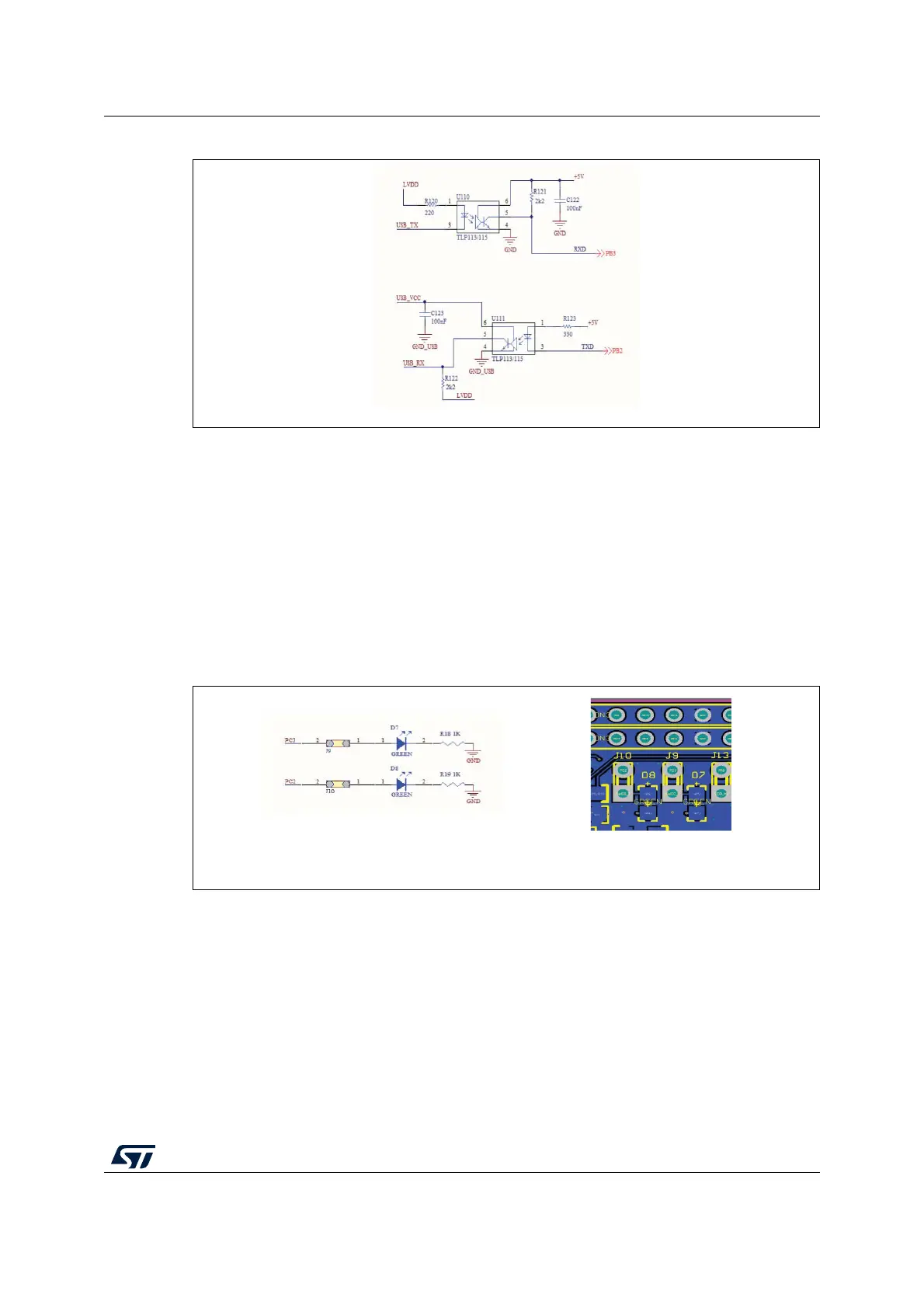
2.6.1 User LEDs
The LEDs D7 and D8 are available for user purpose; the jumpers J9, J10 connect the 2
LEDs to the microcontroller I/O PC3 and PC2 respectively. The HW connection is reported
in Figure 10: User D7 and D8 LEDs.
Figure 10. User D7 and D8 LEDs
2.6.2 Push button
A push button is connected to GPIO PA11. The pin is connected to High level by a 10 kΩ
pull-up resistor and it is set to Low (GND) when the button is pushed; a low pass filter has
been added to reduce the noise and clean spurious signals.