Hardware overview UM1681
12/23 UM1681 Rev 3
2.5 USB and Graphic User Interface (GUI)
One of the two FTDI2232 channels has been configured for implementing a serial
communication between PC USB and microcontroller UART, both for serial booting or for
controlling the microcontroller using a dedicated GUI.
The USB section (serial communication) is electrical insulated with respect to all the circuitry
adding opto-couplers in series to the path of TX and SX signals (see Figure 9: GUI: TX and
RX signals with optocoupler).
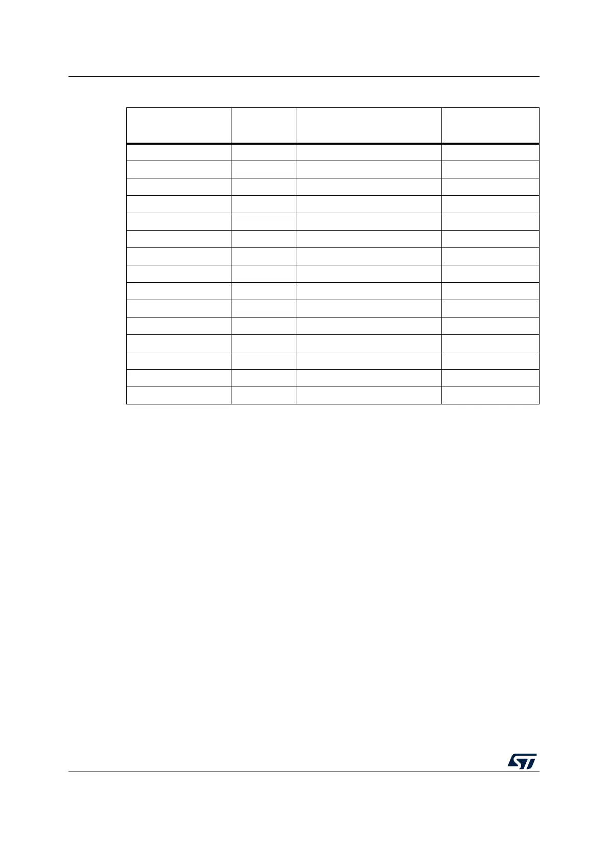
Table 3. Programming and debug - Jumper setting
Jumper name JTAG
USB
(Integrated debugger)
PLS Adapter
J101 Open Close Close
J102 Open Close Close
J103 Open Close Close
J105 Open Close Close
J109 Open Close Close
J110 Open Close Close
J111 Open Close Close
J114 Open Close Close
J19 Open Open Close
J20
(1)
1. J20 connect the GND of the board to the GND of the USB input. This jumper should be removed when the
USB section must be electrically insulated
Close Close Close
S1
(2)
2. S1 is used as power switch; if S1 is left open, the 12 V form external source does not supply the board
Close Close Open
S2
(3)
3. If S2 is present and the 12 V supply comes from the daughters boards, J16 must be left unconnected (no
external PSU must be powered and connected).
Open Open Open
J1 Close Close Close
J2 Close Close Close
J3 Close Close Close