EasyManua.ls Logo

ST STM32F103RET6 - User Manual

ST STM32F103RET6
39 pages
Print Icon
To Next Page IconTo Next Page
Loading...
Introduction
The STEVAL-MKI109V2 (eMotion) is a motherboard designed to provide the user with a complete ready-to-use platform for the
demonstration of MEMS devices mounted on adapter boards.
The STEVAL-MKI109V2 uses an STM32F103RET6 microcontroller which functions as a bridge between the sensor on the
adapter board and the PC on which it is possible to use the Unico graphical user interface (GUI) downloadable from the ST
website or dedicated software routines for customized applications.
This user manual describes the hardware included with the demonstration kit and provides the information required to install the
demonstration board and how to upgrade the firmware of the microcontroller.
For details regarding the features of each sensor, please refer to the datasheet available for each individual device.
STEVAL-MKI109V2: eMotion motherboard for MEMS adapter boards
UM0979
User manual
UM0979 - Rev 6 - February 2018
For further information contact your local STMicroelectronics sales office.
www.st.com/
Downloaded from Arrow.com.

Table of Contents

Question and Answer IconNeed help?

Do you have a question about the ST STM32F103RET6 and is the answer not in the manual?

Overview

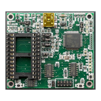
The STEVAL-MKI109V2 (eMotion) is a motherboard designed to provide a complete ready-to-use platform for the demonstration of MEMS devices mounted on adapter boards. This user manual describes the hardware included with the demonstration kit and provides the information required to install the demonstration board and how to upgrade the firmware of the microcontroller.

The STEVAL-MKI109V2 uses an STM32F103RET6 microcontroller, which functions as a bridge between the sensor on the adapter board and the PC. It is possible to use the Unico graphical user interface (GUI), downloadable from the ST website, or dedicated software routines for customized applications.

Function Description

The STEVAL-MKI109V2 is a demonstration kit designed to facilitate the evaluation and development of MEMS sensors. It acts as an interface between a MEMS adapter board and a PC, allowing users to acquire data from the sensors, process it, and visualize it using the Unico GUI or custom software. The board supports both digital and analog MEMS sensors, and its architecture is designed for ease of use and flexibility.

Important Technical Specifications

  • Microcontroller: STM32F103RET6. This microcontroller is central to the board's operation, handling communication between the MEMS sensor and the PC, as well as data processing.
  • Supported Sensors: The board supports a wide range of ST MEMS adapter boards, including accelerometers, gyroscopes, magnetometers, pressure sensors, and humidity sensors. A comprehensive list of supported adapter boards and their corresponding devices is provided in the manual (e.g., STEVAL-MKI009V1 with LIS3LV02DL, STEVAL-MKI108V2 with 9AXISMODULE [LSM303DLHC + L3GD20]).
  • Communication Interfaces:
    • USB: The primary interface for connecting to a PC. It provides power to the board and enables data transfer.
    • DIL24 Connector: This connector is used to interface with the MEMS adapter boards.
    • GPIOs: The STM32 GPIOs are connected directly to the interrupt pins of digital adapters and the power/USB LED.
  • Power Supply: The board is powered via the USB connection.
  • LED Indicators: Six LEDs are integrated into the eMotion board:
    • D1 (Blue): Power supply indicator.
    • D2 and D3 (Green): Directly connected to the interrupt pins of the MEMS digital adapters.
    • D4, D5, and D6 (Red): General-purpose LEDs, used to indicate firmware states or specific firmware selected from those available. D5 indicates that the microcontroller is well configured with the sensor, and D4 blinks according to the sensor data rate selected.
  • Buttons: Two buttons are available:
    • SW1 (Reset): Used to reset the STM32.
    • SW2 (User): Used to select the STM32 boot mode.
  • Jumpers: Several jumpers are present on the board for configuration:
    • JP4: Jumper for power-down (PD), self-test (ST), and high-pass filter reset (HP) modes.
    • JP7: Used to select either JTAG (JP7 unfiled) or SWD (JP7 fitted) mode.
    • JP1: Allows the user to measure the sensor current consumption by connecting a multimeter in series with the terminals.
    • JP3, JP5, and JP6: Used to manually set some features which are available for just some of the analog MEMS adapters.
    • JP2: Used to set the self-test feature.
    • JP5: To handle the power-down and high-pass filter when they are fitted on pins 2-3.

Usage Features

  • Demonstration Kit Setup:

    1. Connect the eMotion to the USB port.
    2. Launch an application which allows to send commands through the virtual serial port. The manual recommends using Microsoft® HyperTerminal® program available with the Windows XP operating system.
    3. Create a new connection, enter a name (e.g., "STEVAL-MKI109V2"), and click "OK".
    4. In the "Connect Using" field, select the virtual COM port which the USB port has been mapped, and click "OK".
    5. In port settings, set bits per second to 115200, data bits to 8, parity to none, stop bits to 1, and flow control to none. Click "OK".
    6. In the HyperTerminal® application window, choose "files" > "properties" > "settings", then click on the "ASCII Setup" button.
    7. Select "Send line ends with line feeds" and "Echo typed characters locally".
    8. Click the "OK" button to close the "ASCII Setup" window.
    9. Click the "OK" button to close the "Properties" window. Once these procedures have been completed, the user can utilize the commands described in the following sections by typing them in the "HyperTerminal" window.
  • Software Installation:

    • The software package can be downloaded from the st.com website and includes the following directory structure:
      • DRIVER: Contains the installation package for the USB drivers needed to connect the eMotion board to the PC.
      • DFU: Contains the DFU files and the installation package for the software needed to upgrade the firmware of the eMotion board.
      • FIRMWARE: Contains the source code of the firmware of the eMotion board together with the corresponding binary file that can be flashed to the board using the DFU software.
    • Hardware Installation (Windows platforms): No driver installation is needed on Linux and Mac OS platforms. To install the STM32 virtual COM port driver on Windows platforms, launch the "VCPdriver_V1.4.0_Setup.exe" included in the Windows installation package under the "DRIVER" folder and follow the instructions on the screen. Once the driver is installed, insert the demonstration kit board into a free USB port. A notification message should appear, as shown in Figure 5.
    • DFU (Device Firmware Upgrade): The MEMS STEVAL-MKI109V2 demonstration board is capable of reprogramming an application through the USB, in accordance with the DFU class specification defined by the USB implementation Forum. This capability is useful because it allows reprogramming the microcontroller directly in the field and is particularly well-suited to USB applications where the same USB connector can be used both for the standard operating mode and for the reprogramming process.
      • DFU on Windows: To install the DFU software, launch the "DFuse_Demo_V3.0.5_Setup.exe" included in the software package under the "DFU" folder and follow the instructions on the screen. To launch the software, select "Start > STMicroelectronics > DFUSe > DFUSe Demonstration". To upgrade or verify action, select the DFU Demo tool, click on the 'Choose...' button and select the target .dfu file; then click the 'Upgrade' button to start the firmware upgrade.
      • DFU on Linux: The DFU program used for Linux operating systems is 'dfu-util'. The procedure for Ubuntu Linux operating systems is described.
      • DFU on Mac OS: The DFU program used for Mac operating systems is 'dfu-util'. Before installing it, you need to install Homebrew.
  • Supported Commands: The microcontroller mounted on the eMotion board is equipped with dedicated firmware that supports a set of commands which allow to control either the digital or the analog output MEMS sensor and permits the acquisition of the measured data. The firmware also handles the communication between the board and the PC through the USB bus. These features allow the user to easily write their own applications to exploit the capabilities of the user chosen.

    • *setbXXXXY: Selects firmware according to the adapter connected.
    • *start: Starts continuous data acquisition.
    • *debug: Returns the output data in readable text format.
    • *stop: Stops data acquisition.
    • *Zon: Forces 3-state.
    • *Zoff: Exits from 3-state.
    • *dev: Device name.
    • *ver: Firmware version.
    • *rAA: Accelerometer register read.
    • *wAADD: Accelerometer register write.
    • *single: It gets a single X, Y, and Z data acquisition.
    • *list: Prints the list of MKIs supported.
    • *listdev: Prints the list of devices supported.
    • *echoon: Activates the write verbose mode.
    • *echooff: Deactivates the write verbose mode.
    • *fiforst: Accelerometer "Reset mode" enable.
    • *fifomde: Accelerometer "FIFO mode" enable.
    • *fifostr: Accelerometer "FIFO Stream" enable.
    • *fifostf: Accelerometer "Stream-to-FIFO" enable.
    • *fifobtf: Accelerometer "Bypass-to-FIFO" enable.
    • *fifobts: Accelerometer "Bypass-to-Stream" enable.
    • *fifodstr: Accelerometer "Dynamic Stream" enable.
    • *grAA: Gyroscope register read.
    • *gwAADD: Gyroscope register write.
    • *gfiforst: Gyroscope "Reset mode" enable.
    • *gfifomde: Gyroscope "FIFO mode" enable.
    • *gfifostr: Gyroscope "FIFO Stream" enable.
    • *gfifostf: Gyroscope "Stream-to-FIFO" enable.
    • *gfifobtf: Gyroscope "Bypass-to-FIFO" enable.
    • *gfifobts: Gyroscope "Bypass-to-Stream" enable.
    • *gfifodstr: Gyroscope "Dynamic Stream" enable.
    • *mrAA: Magnetometer register read.
    • *mwAADD: Magnetometer register write.
    • *mfiforst: Magnetometer "Reset mode" enable.
    • *mfifomde: Magnetometer "FIFO mode" enable.
    • *mfifostr: Magnetometer "FIFO Stream" enable.
    • *mfifostf: Magnetometer "Stream-to-FIFO" enable.
    • *mfifobtf: Magnetometer "Bypass-to-FIFO" enable.
    • *mfifobts: Magnetometer "Bypass-to-Stream" enable.
    • *mfifodstr: Magnetometer "Dynamic Stream" enable.
    • *prAA: Pressure sensor register read.
    • *pwAADD: Pressure sensor register write.
    • *pfiforst: Pressure sensor "Reset mode" enable.
    • *pfifomde: Pressure sensor "FIFO mode" enable.
    • *pfifostr: Pressure sensor "FIFO Stream" enable.
    • *pfifostf: Pressure sensor "Stream-to-FIFO" enable.
    • *pfifobtf: Pressure sensor "Bypass-to-FIFO" enable.
    • *pfifobts: Pressure sensor "Bypass-to-Stream" enable.
    • *pfifodstr: Pressure sensor "Dynamic Stream" enable.
    • *hrAA: Humidity sensor register read.
    • *hwAADD: Humidity sensor register write.
    • *PDON: Sets power-down pin.
    • *PDOFF: Clears power-down pin.
    • *STON: Sets self-test pin.
    • *STOFF: Clears self-test pin.
    • *HPON: Sets high-pass filter pin.
    • *HPOFF: Clears high-pass filter pin.
    • *FSON: Sets full-scale pin.
    • *FSOFF: Clears full-scale pin.

Maintenance Features

  • Firmware Upgrade: The DFU utility allows users to upgrade the firmware of the eMotion board. This is crucial for incorporating new features, bug fixes, or supporting new MEMS devices. The manual provides detailed instructions for DFU on Windows, Linux, and Mac OS platforms.
  • Troubleshooting: The manual implicitly supports troubleshooting by providing detailed setup instructions and command descriptions. If the device is not functioning as expected, users can verify the installation steps, check the virtual COM port assignment, and ensure the correct commands are being used.
  • Hardware Maintenance: The bill of materials (BOM) for the STEVAL-MKI109V2 is provided, listing all components with their designators, descriptions, comments, and footprints. This information is valuable for advanced users who might need to replace components or understand the board's construction for repair purposes.
  • Documentation and Support: The manual itself serves as a primary maintenance resource, offering comprehensive information on the device's functionality, usage, and technical specifications. STMicroelectronics also provides additional support through their website, including software downloads and potentially updated documentation.

ST STM32F103RET6 Specifications

General IconGeneral
BrandST
ModelSTM32F103RET6
CategoryMotherboard
LanguageEnglish

Related product manuals