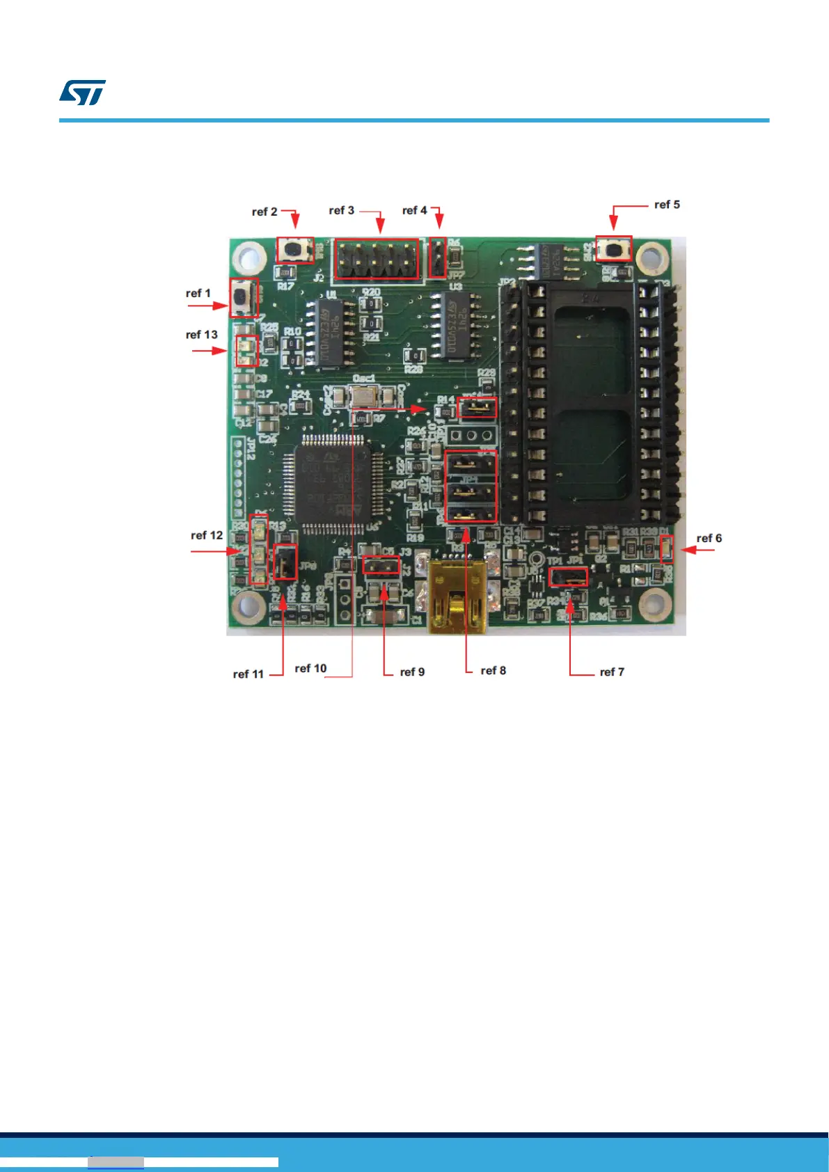
Figure 3. Board top view
In order to use the eMotion demonstration kit, installation of a dedicated driver is required, which is included in the
installation pack, together with a GUI interface which allows simple interaction with the sensor. The steps required
for driver and software installation are described in the following sections.
In Figure 3. Board top view some main components placed on the top layer of the eMotion kit are highlighted.
• Jumpers JP9 and JP10 (Figure 3. Board top view, ref 10, ref 11) are used to select the STM32 boot mode.
When the eMotion is used together with MEMS adapters, JP9 and JP10 must be fitted (see STM32
datasheet for more information).
• Jumper J2 (Figure 3. Board top view, ref 7) can be used to directly supply the board (from 3.5 V to 6 V)
instead of using the USB connector.
• Jumper JP1 allows the user to measure the sensor current consumption by connecting a multimeter in
series with its terminals (Figure 3. Board top view, ref 9).
• Jumpers JP4, JP5, and JP6 (Figure 3. Board top view, ref 8) are used to manually set some features which
are available for just some of the analog MEMS adapters (see Table 1. Jumper configuration for power-down
(PD), self test (ST), and high-pass filter reset (HP) for more details). JP4 is used to set the self-test feature,
JP5 to handle the power-down pin, and JP6 to reset the MEMS high-pass filter. When they are fitted on pins
2-3, these functions are handled by the firmware itself.
UM0979
Demonstration kit description
UM0979 - Rev 6
page 4/39
Downloaded from Arrow.com.Downloaded from Arrow.com.Downloaded from Arrow.com.Downloaded from Arrow.com.