Hardware layout UM1842
26/35 DocID027213 Rev 1
- - - - - - - - - - - - -
VDD
- -4 -
-- - - -----
GND
GND
- -
GND
531 -
- - - - - - - - - - - - -
GND
- -2 -
- - - - - - - - - - - - -
GND
- -5 -
- - - - - - - - - - - - -
GND
- -23-
- - - - - - - - - - - - -
GND
- -49 -
- - - - - - - - - - - -
GND
--50 -
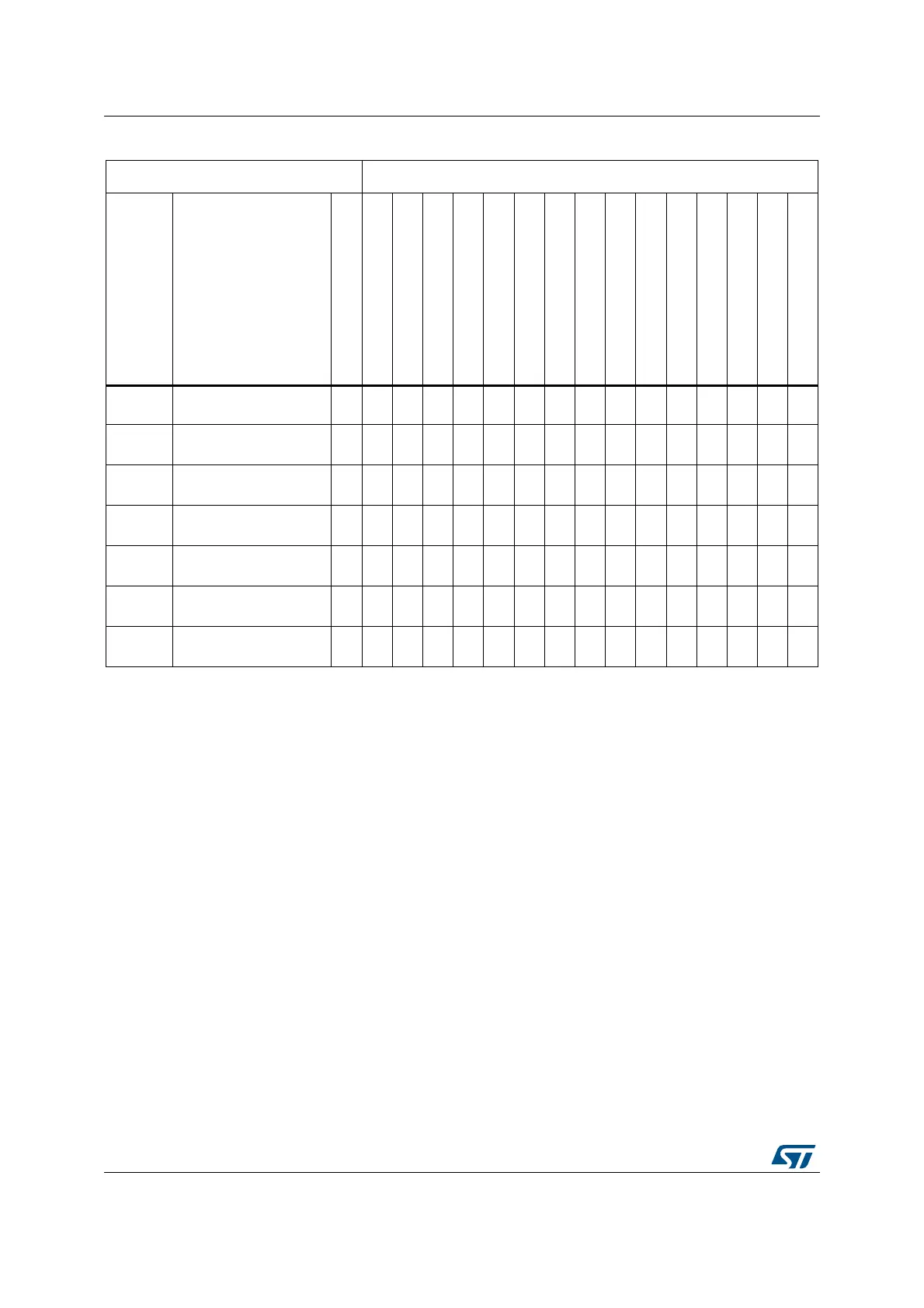
1. The default configuration for the functions used on the boards, is shown in grey color.
Table 5. MCU pin description versus board function (page 8 of 8)
(1)
(continued)
MCU pin Board function
Main
function
Alternate
functions
LQFP100
CS43L22
MP45DT02
L3GD20
LSM303DLHC
Pushbutton
LED
SWD
USB
OSC
Free I/O
Power supply
CN5
CN2
P1
P2