EasyManua.ls Logo

ST STM32G0 User Manual

ST STM32G0
26 pages
To Next Page IconTo Next Page
To Previous Page IconTo Previous Page
Page #15 background image
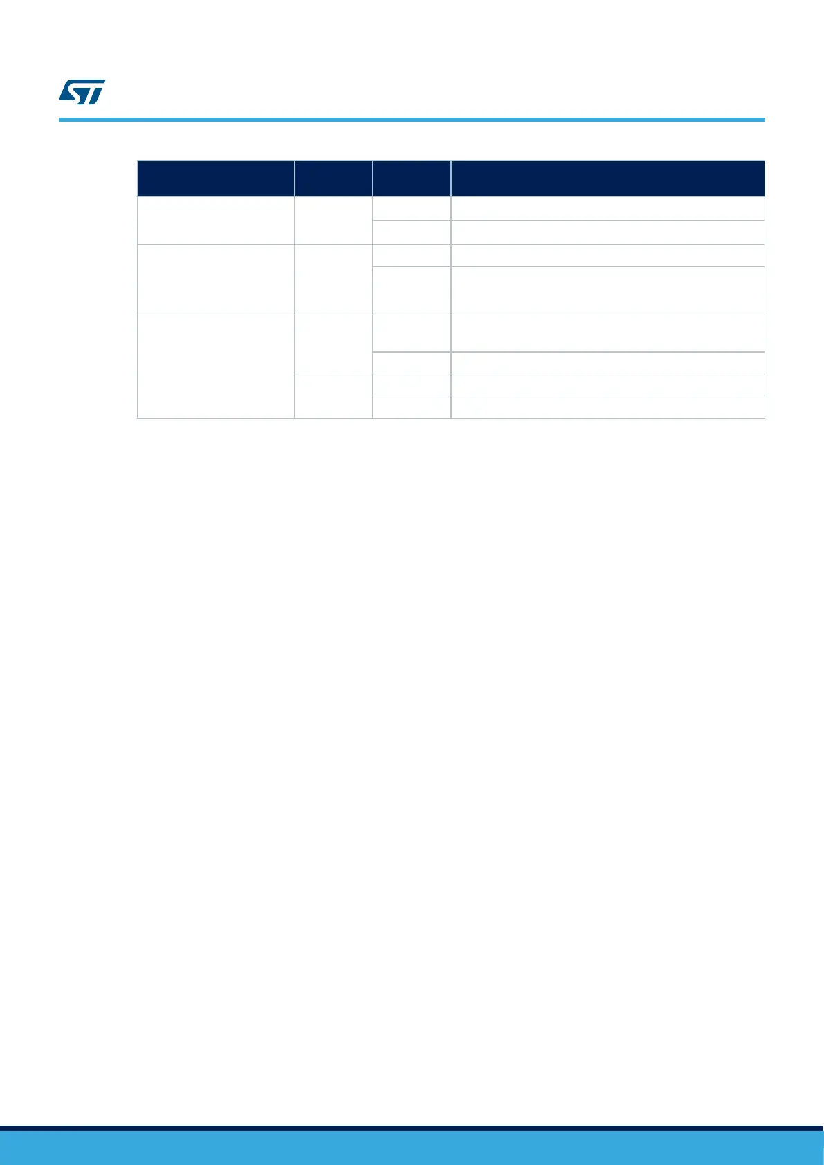
Solder bridge control
Solder
bridge (SB)
State
(1)
Description
(1)
AREF SB10
ON
AREF Arduino
signal connected to 3.3 V
OFF
AREF Arduino
signal not connected to 3.3 V
3.3 V voltage regulator SB11
ON 3.3 V main voltage regulator output enabled
OFF
3.3 V main voltage regulator output disabled (useful when
powering the STM32G0 Nucleo-32 with a 3.3 V applied on
CN4 pin 14)
USER LED
SB12
ON
USER LED driven by STM32G0 PB3 also connected to
Arduino
D13 pin
OFF USER LED not driven by STM32G0 PB3
SB13
ON USER LED driven by STM32G0 PC6
OFF USER LED not driven by STM32G0 PC6
1. The default SB state is in bold.
UM2591
Solder bridges
UM2591 - Rev 1
page 15/26
Question and Answer IconNeed help?

Do you have a question about the ST STM32G0 and is the answer not in the manual?

ST STM32G0 Specifications

General IconGeneral
SeriesSTM32G0
CoreARM Cortex-M0+
Operating FrequencyUp to 64 MHz
ADC Resolution12-bit
Operating Voltage1.7 V to 3.6 V
Communication InterfacesUSART, SPI, I2C, USB, CAN
Operating Temperature-40°C to 85°C
Package OptionsLQFP, UFQFPN, TSSOP

Summary

Introduction

Ordering Information

Product Marking

Details on product marking for identification and traceability.

Products and Codification

Explanation of product codification and available variants.

Development Environment

System Requirements

Specifies the necessary system requirements for development.

Development Toolchains

Lists supported development toolchains and IDEs for the board.

Demonstration Software

Information about preloaded demonstration software and its source.

Quick Start

Getting Started

Provides initial steps and guidance for starting with the Nucleo-32 board.

Hardware Layout and Configuration

PCB Layout

Details the physical layout of components on the PCB, including top and bottom views.

Mechanical Drawing

Shows the mechanical dimensions and drawings of the board.

Embedded ST-LINK/V2-1

Information about the integrated ST-LINK/V2-1 debugger and firmware upgrade.

Power Supply

Details board power supply options via USB and external sources, with configuration details.

Board Functions

Describes board functions including LEDs, push-button, current measurement, and VCP.

Solder Bridges

Explains the configuration and function of various solder bridges on the board.

Board Connectors

Arduino™ Nano V3 Connectors CN3 and CN4

Details the Arduino Nano V3 compatible connectors and their pinout.

Federal Communications Commission (FCC) and Industry Canada (IC) Compliance Statements

FCC Compliance Statement

FCC compliance information, including Part 15 rules and user modifications.

IC Compliance Statement

Industry Canada (IC) compliance statement and identification.

CE Conformity

Warning

Warning regarding CE conformity for Class A product and potential radio interference.

Revision History

Related product manuals