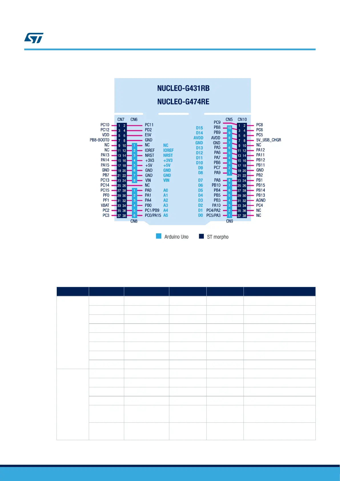
Figure 18. Arduino
™
and ST morpho connectors pinout
Note:
Arduino
™
Uno V3 D0 and D1 signals are connected by default on USART1 (MCU I/O PC4 and PC5). For details
about how to modify the UART interface, refer to Section 6.6.5 Virtual COM port (VCP): LPUART and USART.
Table 15. Arduino
™
connectors pinout
Connector
Pin number Pin name Signal name
STM32 pin
(1)
Function
(1)
CN6
1 NC - - Reserved for test
2 IOREF - - I/O reference
3 NRST NRST PG10-NRST RESET
4 3V3 - - 3V3 input/output
5 5V - - 5 V output
6 GND - - GND
7 GND - - GND
8 VIN - - 7 V - 12 V input power
CN8
1 A0 ADC PA0 ADC12_IN1
2 A1 ADC PA1 ADC12_IN2
3 A2 ADC PA4 ADC2_IN17
4 A3 ADC PB0 ADC3_IN12 or ADC1_IN15
5 A4 ADC
PC1/
PB9
ADC12_IN7/
I2C1_SDA
6 A5 ADC
PC0/
PA15
ADC12_IN6/
I2C1_SCL
UM2505
Arduino™ Uno V3 connectors CN5, CN6, CN8 and CN9
UM2505 - Rev 2
page 30/43

 Loading...


