List of figures
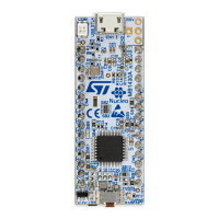
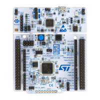
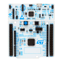
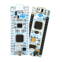
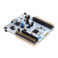
Figure 1. NUCLEO-G474RE top view ...........................................................1
Figure 2. NUCLEO-G474RE bottom view ........................................................1
Figure 3. Hardware block diagram .............................................................7
Figure 4. Top layout .......................................................................8
Figure 5. Bottom layout .....................................................................9
Figure 6. STM32G4 Nucleo 64 board mechanical drawing (in millimeter) .................................. 10
Figure 7. USB composite device.............................................................. 11
Figure 8. Connecting an external debug tool to program the on-board STM32G4 ............................ 12
Figure 9. STM32G4 Nucleo-64 board power tree .................................................. 14
Figure 10. Power supply input from STLINK-V3E USB connector with PC (5 V, 500 mA max) .................... 15
Figure 11. Power supply input from VIN (7 V - 12 V, 800 mA max) ....................................... 17
Figure 12. Power supply input from 5V_EXT (5 V, 500 mA max)......................................... 18
Figure 13. Power supply input from ST-LINK USB connector with USB charger (5 V) .......................... 19
Figure 14. Power supply input from external 3V3 ................................................... 21
Figure 15. USB Micro-B connector CN1 (front view) ................................................. 28
Figure 16. MIPI10 connector CN4 ............................................................. 28
Figure 17.
Arduino
™
connectors............................................................... 29
Figure 18.
Arduino
™
and ST morpho connectors pinout .............................................. 30
Figure 19. ST morpho connectors ............................................................. 32
UM2505
List of figures
UM2505 - Rev 2
page 42/43
 Loading...
