6.3.3 Using an external debug tool to program and debug the on-board STM32
There are two basic ways to support an external debug tool:
1. Keep the embedded STLINK-V3E running. Power on the STLINK-V3E at first until the COM LED turns red.
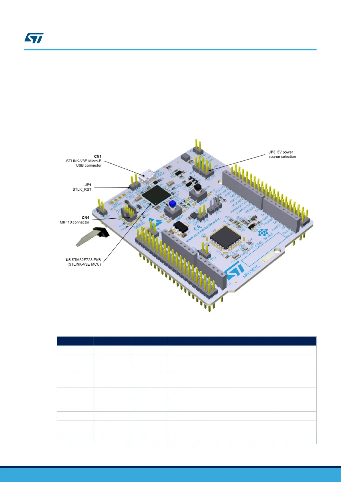
Then connect the external debug tool through the CN4 STDC14/MIPI-10 debug connector
2. Set the embedded STLINK-V3E in hig-impedance state: when jumper JP1 (STLK_RST) is ON, the
embedded STLINK-V3E is in RESET state and all GPIOs are in high-impedance; then, connect the external
debug tool to debug connector CN4.
Figure 8. Connecting an external debug tool to program the on-board STM32G4
Table 5. MIPI10 / STDC14 debug connector (CN4)
MIPI10 pin
STDC14 pin CN4 Function
- 1 NC Reserved
- 2 NC Reserved
1 3 3V3 Target VCC
2 4 T_SWDIO
Target SWDIO using SWD protocol or Target JTMS (T_JTMS) using
JTAG protocol
3 5 GND Ground
4 6 T_SWCLK
Target SWCLK using SWD protocol or Target JCLK (T_JCLK) using
JTAG protocol
5 7 GND Ground
6 8 T_SWO
Target SWO using SWD protocol or Target JTDO (T_JTMS) using
JTAG protocol
7 9 NC Not connected
UM2505
Embedded STLINK-V3E
UM2505 - Rev 2
page 12/43

 Loading...


