High-resolution timer (HRTIM) RM0440
954/2126 RM0440 Rev 4
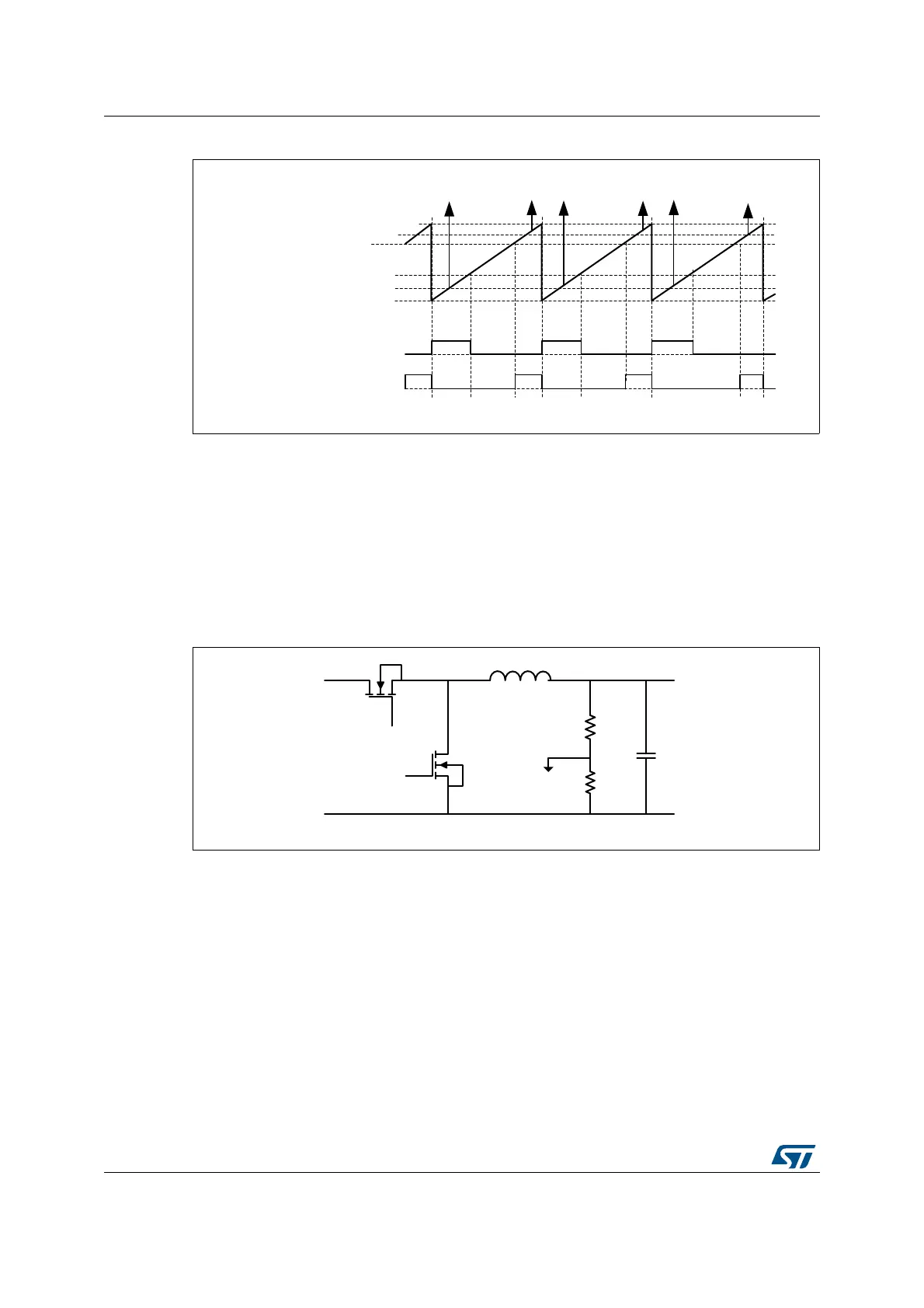
Figure 262. Dual Buck converter management
Timers A..E provide either 12 buck converters coupled by pairs (both with identical switching
frequencies) or 7 completely independent converters (each of them having a different
switching frequency), using the master timer as the 7
th
time base.
27.4.2 Buck converter with synchronous rectification
Synchronous rectification allows to minimize losses in buck converters, by means of a FET
replacing the freewheeling diode. Synchronous rectification can be turned on or off on the fly
depending on the output current level, as shown on Figure 263.
Figure 263. Synchronous rectification depending on output current
The main difference versus a single-switch buck converter is the addition of a deadtime for
an almost complementary waveform generation on HRTIM_CHA2, based on the reference
waveform on HRTIM_CHA1 (see Figure 264).
MS32344V2
PER
CMP2
CMP1
ADC ADC
ADC
TIMA
counter
TIMA
outputs
CMP4
CMP3
HRTIM_CHA1
(BUCK 1)
HRTIM_CHA2
(BUCK 2)
ADC
ADC
ADC
MS32345V3
HRTIM_
CHA1
HRTIM_
CHA2
V
IN
V
OUT
ADC