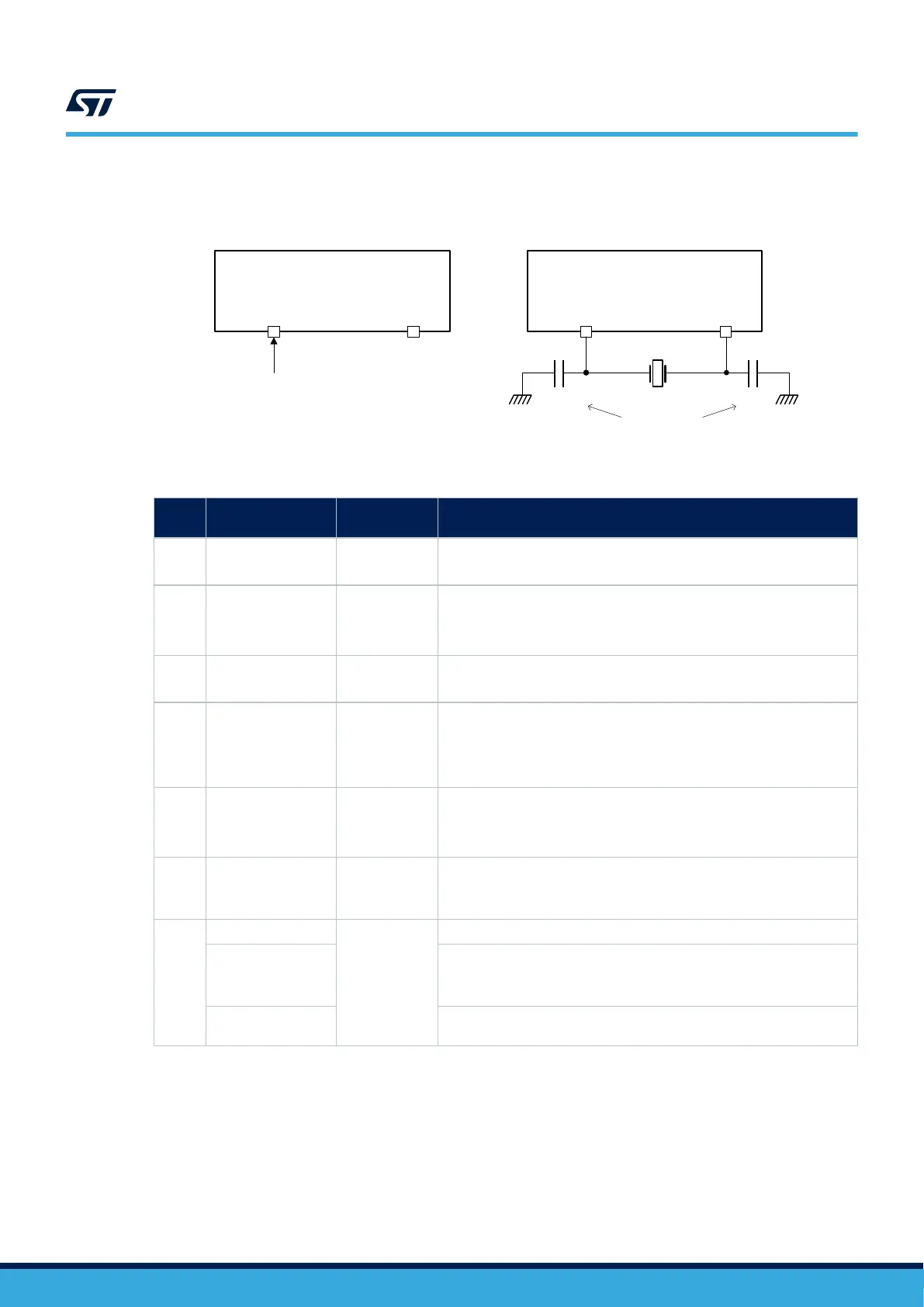
Figure 11. HSE/LSE clock source
OSC_IN
OSC_OUT
External clock
source
OSC32_IN OSC32_OUT
(HiZ)
OSC_IN
OSC_OUT
Load
capacitors
OSC32_IN OSC32_OUT
C
L1
C
L2
External clock configuration Crystal/ceramic resonators configuration
Table 4. Clock source generation
Source Frequency range
External
component
Comments
HSE 4 to 50 MHz Yes
High Speed External clock
Used when a very accurate high speed clock is needed.
LSE
32.768 kHz
(max 1 MHz)
Yes
Low Speed External clock
Used when a very accurate low speed clock is needed.
For instance for the real time clock (RTC).
HSI 64 MHz No
High Speed Internal Clock
Default system clock after a reset.
HSI48 48 MHz No
High Speed Internal 48 MHz clock
Kernel clock for some peripherals.
High precision clock for USB with Clock Recovery System which can use
the USB SOF signal.
CSI 4 MHz No
Low Power Internal oscillator
Faster start-up time than HSI
Can be used for wake-up from Stop mode
LSI 32 KHz No
Low Speed Internal clock, for independent watchdog (IWDG), RTC and
auto-wakeup unit (AWU).
This clock can run in Stop or Standby modes.
PLL
2 to 16 MHz input
No
Wide-range mode
1 to 2 MHz input
Low-range mode
Some specific frequencies obtained with integer ratio which may be
needed for some application (e.g. Audio).
192 to 836 MHz VCO
output
Integer or fractional ratios supported for all PLLs.
To optimize power consumption, each clock source can be switched on or off independently when it is not used.
Refer to the reference manual STM32H723/733, STM32H725/735 and STM32H730 advanced Arm
®
-based 32-bit
MCUs (RM0468) for a detailed description of the clock tree. This document provides a complete view of clock
usage by peripheral is provided in the Kernel clock distribution overview.
AN5419
Introduction
AN5419 - Rev 2
page 21/50
 Loading...


