9.2 Crystal oscillator
Use the application note: Oscillator design guide for STM8S, STM8A and STM32 microcontrollers (AN2867), for
further guidance on how to layout and route crystal oscillator circuits.
9.3 Power supply decoupling
An adequate power decoupling for STM32H723/33, STM32H725/35 and STM32H730 microcontrollers is
necessary to prevent excessive power and ground bounce noise. Refer to Section 2 Power supplies.
The following recommendations shall be followed:
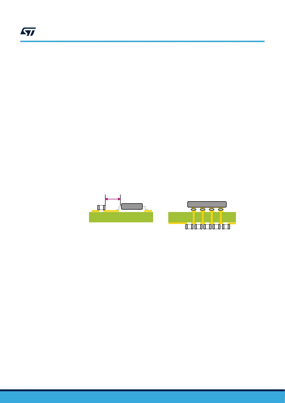
• Place the decoupling capacitors as close as possible to the power and ground pins of the MCU. For BGA
packages, it is recommended to place the decoupling capacitors on the opposing side of the PCB (see
Figure 19. Decoupling capacitor placement depending on package type).
• Add the recommended decoupling capacitors to as many V
DD
/V
SS
pairs as possible.
• Connect the decoupling capacitor pad to the power and ground plane with a wide and short trace/via. This
reduces the series inductance, maximizes the current flow and minimizes the transient voltage drops from
the power plane and in turn reduces the ground bounce occurrence.
Figure 20. Example of decoupling capacitor placed underneath shows an example of decoupling capacitor
placement underneath STM32H723/33, STM32H725/35 and STM32H730 microcontroller, closer to the pins and
with less vias.
Figure 19. Decoupling capacitor placement depending on package type
PCB PCB
Decoupling
capacitor
Decoupling capacitor and STM32
MCU on the same side of the
package (all packages except BGA)
Distance to
be minimized
STM32
Decoupling capacitor and STM32
MCU on the opposite sides of the
package (BGA package )
STM32
Decoupling
capacitor
AN5419
Crystal oscillator
AN5419 - Rev 2
page 35/50
 Loading...


