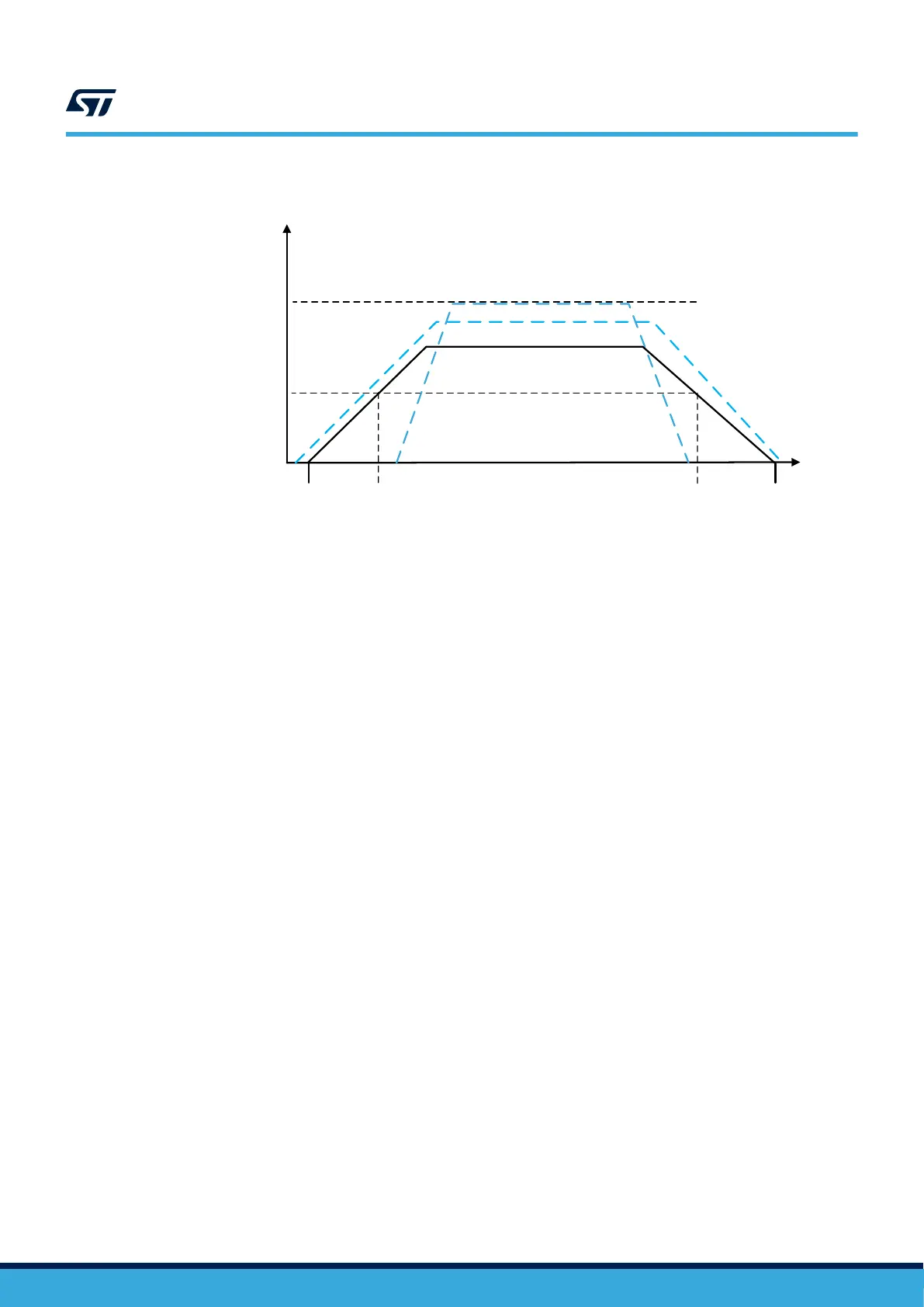
Figure 6. VDD50USB power supply
time
Power-on
Power-
down
Operating mode
V
DD50USB_MAX
= 5.5 V
V
DD50USB_MIN
= 4.0 V
V
DD50USB
V
DD
V
DD50USB
2.1.5 Battery Backup domain
Backup domain description
To retain the content of the RTC Backup registers, Backup SRAM, and supply the RTC when V
DD
is turned off,
the VBAT pin can be connected to an optional 1.2-3.6 V standby voltage supplied by a battery. Otherwise, VBAT
must be connected to another source, such as V
DD
.
When the Backup domain is supplied by V
BAT
(analog switch connected to V
BAT
since V
DD
is not present), the
following functions are available:
• PC14 and PC15 can be used for the LSE pins only.
• PC13 can be used as tamper pin (TAMP1).
• PC1 can be used as tamper pin (TAMP3).
During t
RSTTEMPO
(delay at V
DD
start-up) or after a Power-Down Reset (PDR) is detected, the power switch
between V
BAT
and V
DD
remains connected to VBAT.
During the start-up phase, if V
DD
is established during t
RSTTEMPO
and is greater than V
BAT
+ 0.6 V, a current may
be injected into the VBAT pin through an internal diode connected between V
DD
and the power switch (V
BAT
). If
the power supply/battery connected to the VBAT pin cannot support this current injection, it is strongly
recommended to connect an external low-drop diode between this power supply and the VBAT pin.
Refer to the STM32H72x/73x datasheets for the actual value of t
RSTTEMPO
.
Battery charging
When V
DD
is present, the external battery connected to VBAT can be charged through an internal resistance. This
operation can be performed either through an internal 5 kΩ or 1.5 kΩ resistor. The resistor value can be
configured by software.
Battery charging is automatically disabled in V
BAT
mode.
2.1.6 LDO voltage regulator
The low drop out (LDO) voltage regulator is always enabled after Power-on reset. If it is disabled, it remains
disabled even after any reset source except for a Power-on reset. For system supply configuration where this
regulator is not needed, it will be switched OFF by the user software after system start-up. On some packages,
the LDO power supply is available on external VDDLDO pins. When it is not available on an external pin, V
DDLDO
is connected internally to V
DD
.
For the configuration where the Vcore is supplied by the LDO, the default output level is set to 1.0V (VOS3). Refer
to Figure 2. System supply configuration for more details.
AN5419
Introduction
AN5419 - Rev 2
page 12/50
 Loading...


