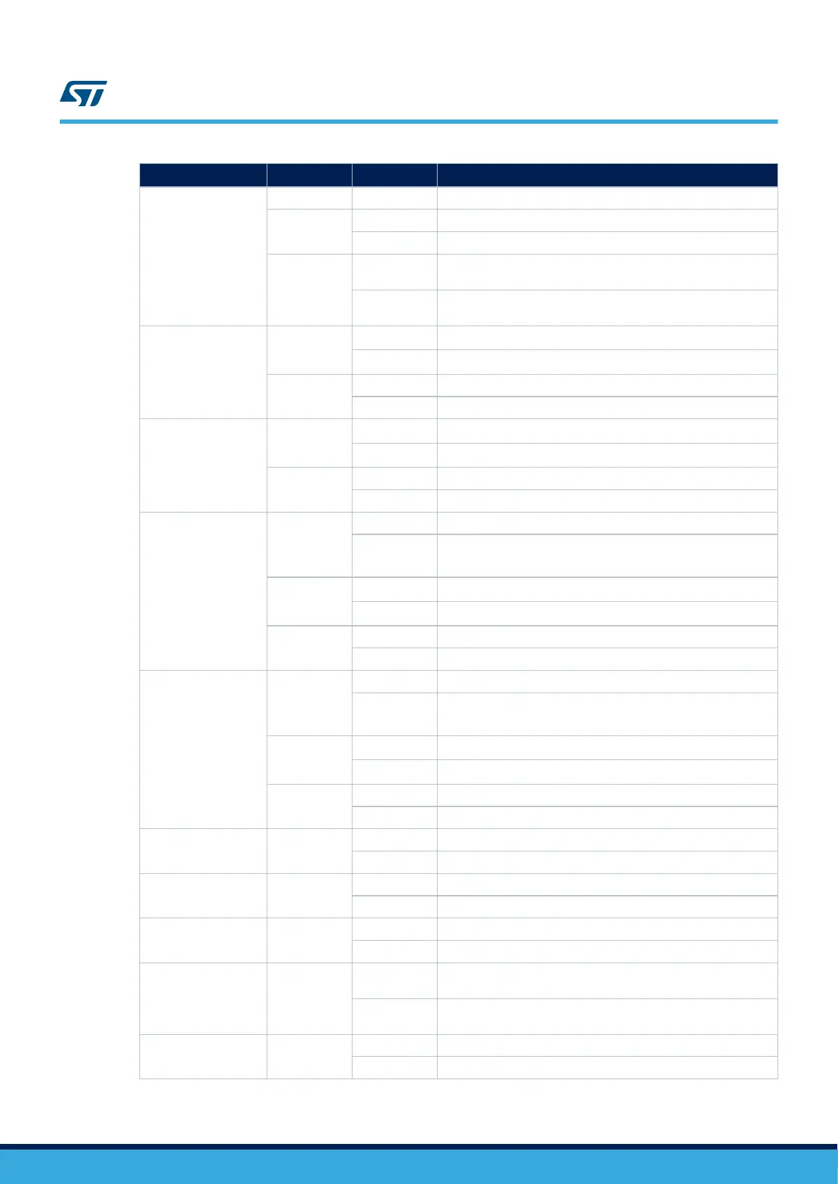
Definition Bridge
Setting
(1)(2)
Comment
Zio SAI_D / SPI_B
interface
SB134
ON PB4 connected to Zio CN7 for SAI_D interface
SB139
OFF PB4 not connected to Zio CN7 for SPI_B interface
ON PB4 connected to Zio CN7 for SPI_B interface
SB135
OFF
PB5 not connected to Zio CN7 for SPI_B interface: Reserved for
UCPD_DB1
ON
PB5 connected to Zio CN7 for SPI_B interface, shared with for
UCPB_DB1
PD8 USART3_TX
SB123
OFF
PD8 USART3_TX not connected to ARDUINO
®
D1 TX
ON
PD8 USART3_TX connected to ARDUINO
®
D1 TX
SB124
OFF PD8 USART3_TX not connected to STLK VCP TX
ON PD8 USART3_TX connected to STLK VCP TX
PD9 USART3_RX
SB125
OFF
PD9 USART3_RX not connected to ARDUINO
®
D0 RX
ON
PD9 USART3_RX connected to ARDUINO
®
D0 RX
SB126
OFF PD9 USART3_RX not connected to STLK VCP RX
ON PD9 USART3_RX connected to STLK VCP RX
PG7 LPUART1_TX
SB127
OFF PG7 LPUART1_TX not connected to STLK VCP TX
ON
PG7 LPUART1_TX connected to STLK VCP TX
Configuration to support debug with 1V8 mode
SB128
OFF
PG7 LPUART1_TX not connected to ARDUINO
®
D1 TX
ON
PG7 LPUART1_TX connected to ARDUINO
®
D1 TX
SB168
OFF PG7 LPUART1_TX not connected to morpho connector CN12
ON PG7 LPUART1_TX connected to morpho connector CN12
PG8 LPUART1_RX
SB129
OFF PG8 LPUART1_RX not connected to STLK VCP RX
ON
PG8 LPUART1_RX connected to STLK VCP RX
Configuration to support debug with 1V8 mode
SB130
OFF
PG8 LPUART1_RX not connected to ARDUINO
®
D0 RX
ON
PG8 LPUART1_RX connected to ARDUINO
®
D0 RX
SB167
OFF PG8 LPUART1_RX not connected to morpho connector CN12
ON PG8 LPUART1_RX connected to morpho connector CN12
MCU VDD_USB SB132
OFF VDD_USB input not supplied
ON VDD_USB input connected to VDD
MCU VDDIO SB133
OFF VDDIO input not supplied (no PG [2-15] I/O)
ON VDDIO input connected to VDD
MCU VDD_USB SB146
OFF VBAT input not supplied
ON VBAT input connected to VDD_MCU 3V3 or 1V8
LSE CLK selection SB147/SB148
OFF
LSE provided by External LSE CLK X2 (R34/R35) PC14 and
PC15 not connected to morpho connector
ON
PC14 and PC15 connected to morpho connector, LSE NOT
provided by External LSE CLK X2
MCU VDDA
SB149
OFF VDDA input not supplied by VDD
ON VDDA input connected to VDD (SB150 must be not connected)
UM2581
Solder bridge configuration
UM2581 - Rev 2
page 32/48

 Loading...


