List of figures
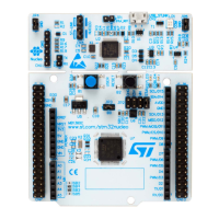
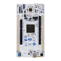
Figure 1. STM32L5 Nucleo-144 board...........................................................1
Figure 2. Default board configuration ...........................................................7
Figure 3. Hardware block diagram .............................................................8
Figure 4. STM32L5 Nucleo-144 board top layout ...................................................9
Figure 5. STM32L5 Nucleo-144 board bottom layout................................................ 10
Figure 6. STM32L5 Nucleo-144 board mechanical drawing (in millimeter) ................................. 11
Figure 7. USB composite device.............................................................. 12
Figure 8. ST-LINK debugger: JP configuration for on-board MCU ....................................... 13
Figure 9. ST-LINK debugger: JP configuration for external MCU........................................ 14
Figure 10. JP6 [1-2]: 5V_STLK Power source ..................................................... 16
Figure 11. JP6 [3-4]: 5V_VIN Power source....................................................... 17
Figure 12. JP6 [5-6]: 5V_EXT Power source ...................................................... 18
Figure 13. JP6 [7-8]: 5V_USB_C Power source ....................................................19
Figure 14. JP6 [9-10]: 5V_CHGR Power source .................................................... 20
Figure 15.
CN15 USB Type-C
™
connector pinout ................................................... 28
Figure 16.
Zio connectors supporting ARDUINO
®
Uno V3 ............................................. 34
Figure 17. ST morpho connector .............................................................. 37
UM2581
List of figures
UM2581 - Rev 2
page 47/48
 Loading...

