• VREF_DDR used to supply the DDR reference voltage
– Value: 1.65 V
• VTT_DDR (LDO3) used to supply the termination resistors of the DDR
– Value: 1.65 V
• 1V8_Audio (LDO1) used to supply the digital/analog of the audio codec
– Value: 1.8 V
• 1V2_HDMI (LDO6) used to supply the digital core and analog part of the HDMI transceiver
– Value: 1.2 V
• 3V3_HDMI (LDO2) used to supply the I/Os of the HDMI transceiver
– Value: 3.3 V
• VDD_USB (LDO4) used to supply the USB phy of the STM32MP157x
– Value: 3.3 V
7.3 Clock sources
7.3.1 LSE clock references
The LSE clock references on the STM32MP157x microprocessor are provided by the external crystal X2:
• 32.768 kHz crystal from NDK : reference NX2012SA
7.3.2 HSE clock references
The HSE clock references on the STM32MP157x microprocessor are provided by the external crystal X6:
• 24 MHz crystal from NDK : reference NX2016SA
7.4 Reset sources
The reset signal of STM32MP157A-DK1 and STM32MP157C-DK2 is active low. The internal PU forces the RST
signal to a high level.
The sources of reset are:
• Reset button B2 (black button)
• STPMIC1
• Embedded ST-LINK/V2.1
• Arduino
™
connector CN16: pin 3, reset from the Arduino
™
board
• STM32MP157x
7.5 Boot mode
7.5.1 Description
At startup, the boot source used by the internal bootROM is selected by the Boot pins. Table 5 describes the
configurations of the Boot pins.
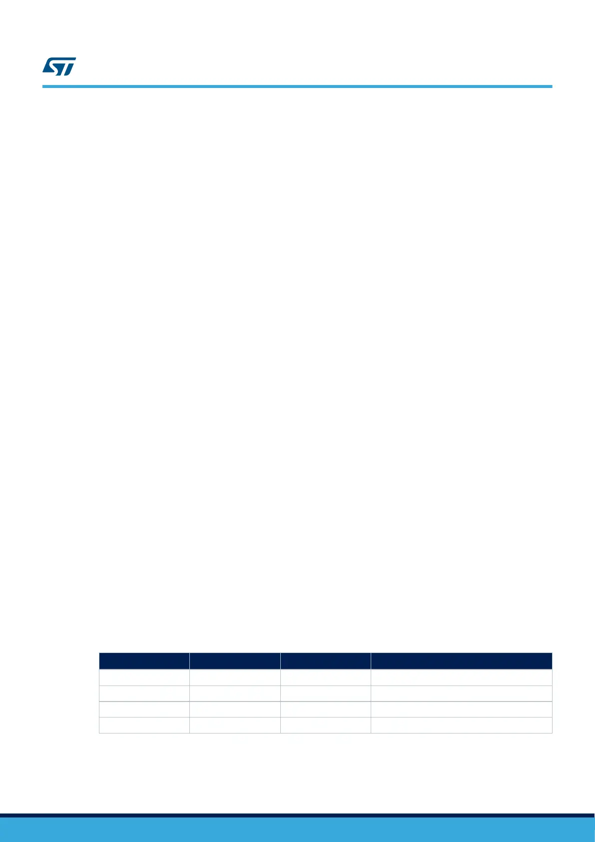
Table 5. Boot mode pins
Boot 0
Boot 1
(1)
Boot 2 Boot mode
0 0 0 Forced USB boot for flashing.
1 0 0 Not supported.
0 0 1 Reserved.
1 0 1 SD card on SDMMC1.
1. Pin Boot 1 is always tied to "0" by a pull-down resistor.
Figure 7 shows the configurations of the boot-related switch SW1.
UM2534
Clock sources
UM2534 - Rev 1
page 12/47