The touch panel power supply is connected to VDD_3V3.
The backlight of the LCD is driven by the STLD40DPUR circuit on the MB1407 board connected to VDD_3V3.
7.14.3 LCD interface
Table 19 describes the I/O configuration of the LCD and CTP interfaces.
Table 19. I/O configuration of the LCD and CTP interfaces
I/O Configuration
DSI_D0P DSI_D0P is used as MIPI-DSI data Lane 0 positive.
DSI_D0N DSI_D0N is used as MIPI-DSI data Lane 0 negative.
DSI_D1P DSI_D1P is used as MIPI-DSI data Lane 1 positive.
DSI_D1N DSI_D1N is used as MIPI-DSI data Lane 0 negative.
DSI_CKP DSI_CKP is used as clock Lane positive.
DSI_DKN DSI_DKN is used as clock Lane negative.
PF2 PF2 is used LCD interrupt lane.
PA15
PA15 is used as DSI backlight control.
(1)
PD12 PD12 used as I2C1_SCL for the touch panel, shared between USB, AUDIO, HDMI.
PF15 PF15 used as I2C1_SDA for the touch panel, shared between USB, AUDIO, and HDMI.
1. Not used. In the default configuration, backlight control is done by the LCD driver.
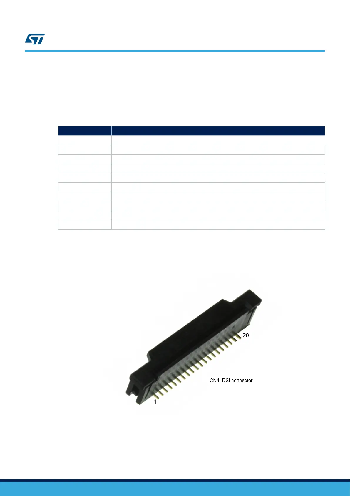
Figure 14 shows the the pinout of LCD connector CN4.
Figure 14. CN4 LCD connector pinout
Table 20 describe the LCD interface and pinout of LCD connector CN4.
UM2534
MIPI DSISM LCD
UM2534 - Rev 1
page 24/47