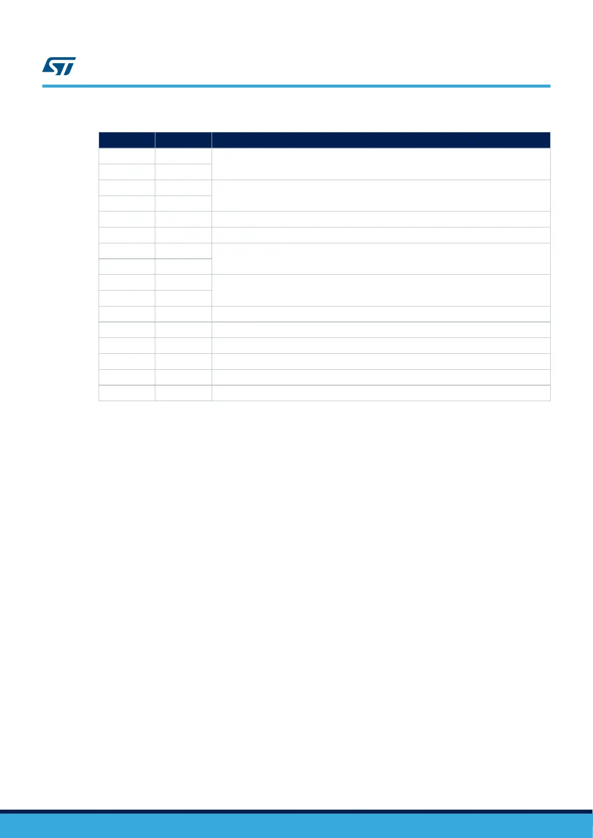
Table 22. CN8 Ethernet connector pinout
Pin Pin name Function
1 TX1+
First bidirectional pair to transmit and receive data.
2 TX1-
3 TX2+
Second bidirectional pair to transmit and receive data.
4 TX2-
5 CT1 Common connected to GND.
6 CT2 Common connected to GND.
7 TX3+
Third bidirectional pair to transmit and receive data.
8 TX3-
9 TX4+
Fourth bidirectional pair to transmit and receive data.
10 TX4-
11 GA Green LED anode.
12 GC Green LED cathode.
13 YA Yellow LED anode.
14 YC Yellow LED cathode.
15 GND GND.
16 GND GND.
7.16
Arduino
™
connectors
7.16.1 Description
The Arduino
™
Uno V3 connectors (CN13, CN14, CN16, and CN17) are available on the STM32MP157A-DK1 and
STM32MP157C-DK2 Discovery kits. Most shields designed for Arduino
™
can fit with the Discovery kits to offer
flexibility in small form factor applications.
7.16.2 Operating voltage
The Arduino
™
Uno V3 connectors support 5 V, 3.3 V, and VDD for I/O compatibility.
Caution:
Do not supply 3.3 V or 5 V from the Arduino
™
shield. Supplying 3.3 V or 5 V from the Arduino
™
shield could
damage the Discovery kit.
7.16.3
Arduino
™
interface
Figure 16 shows the pinout of the Arduino
™
connectors.
UM2534
Arduino™ connectors
UM2534 - Rev 1
page 27/47