Table 21. I/O configuration of the Ethernet interface
I/O Configuration
PG0 PG0 is used as ETH_NRST active Low.
PA2 PA2 is used as ETH_MDIO.
PA6 PA6 is used as ETH_MDINT.
PC1 PB11 is used as ETH_MDC.
PA7 PA7 is used as ETH_RX_DV.
PC4 PB11 is used as ETH_RXD0.
PC5 PB11 is used as ETH_RXD1.
PB0 PB0 is used as ETH_RXD2.
PB1 PB1 is used as ETH_RXD3.
PB11 PB11 is used as ETH_TX_EN.
PG13 PG13 is used as ETH_TXD0.
PG14 PG14 is used as ETH_TXD1.
PC2 PB11 is used as ETH_TXD2.
PE2 PE2 is used as ETH_TXD3.
PA1 PA1 is used as ETH_RX_CLK.
PG4 PG4 is used as ETH_GTX_CLK.
PG5 PG5 is used as ETH_CLK125.
PB5 PB5 is used as ETH_CLK not the default configuration.
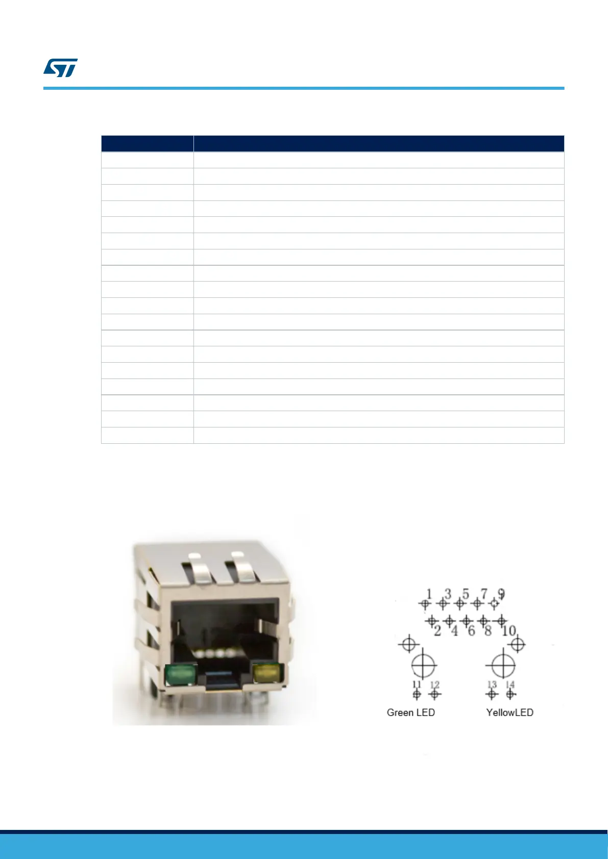
Figure 15 shows the pinout of Ethernet connector CN8.
Figure 15. CN8 Ethernet connector pinout
UM2534
Gigabit Ethernet
UM2534 - Rev 1
page 26/47