6 Debug management
The serial wire/JTAG debug port (SWJ-DP) is an Arm standard CoreSight
™
debug port.
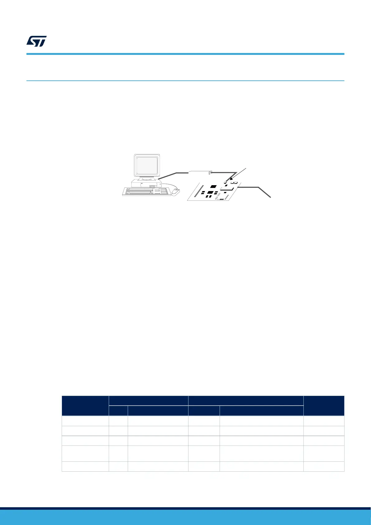
The host/target interface is the hardware equipment that connects the host to the application board. This interface
is made of three components: a hardware debug tool, a serial-wire connector and a cable connecting the host to
the debug tool.
The figure below shows the connection of the host to a development board.
Figure 8. Host-to-board connection
STM32 board
Host PC
Power supply
JTAG/serial-wire connector
Debug tool
The Nucleo demonstration board embeds the debug tools (ST-LINK), so it can be directly connected to the PC
through an USB cable.
6.1 SWJ-DP (serial-wire and JTAG debug port)
The SWJ-DP combines:
• a JTAG‑DP that provides a 5-pin standard JTAG interface to the AHP-AP port
• a SW-DP that provides a 2-pin (clock + data) interface to the AHP-AP port
In the SWJ-DP, the two JTAG pins of the SW-DP are multiplexed with some of the five JTAG pins of the JTAG-DP.
Note: All SWJ-DP port I/Os can be reconfigured to other functions by software, but debugging is no longer possible.
6.2 Pinout and debug port pins
The devices are offered in various packages with different numbers of available pins. As a result, some
functionality related to the pin availability may differ from one package to another.
6.2.1 SWJ-DP pins
Five pins are used as outputs for the SWJ-DP, as alternate functions of the GPIOs (general-purpose I/Os). These
pins, detailed in the table below, are available on all packages.
Table 6. Debug port pin assignment
SWJ-DP pin
JTAG debug port SW debug port
Pin assignment
Type Description Type Debug assignment
JTMS/SWDIO
Input JTAG test mode selection Input/Output Serial‑wire data input/output
PA13
JTCK/SWCLK Input JTAG test clock Input Serial‑wire clock PA14
JTDI Input JTAG test data input - - PA15
JTDO/TRACESWO Output JTAG test data output -
TRACESWO if asynchronous trace
is enabled
PB3
JNTRST Input JTAG test nReset - - PB4
AN5373
Debug management
AN5373 - Rev 1
page 22/37

 Loading...


