UM0671 Evaluation kit board settings
Doc ID 15330 Rev 4 9/23
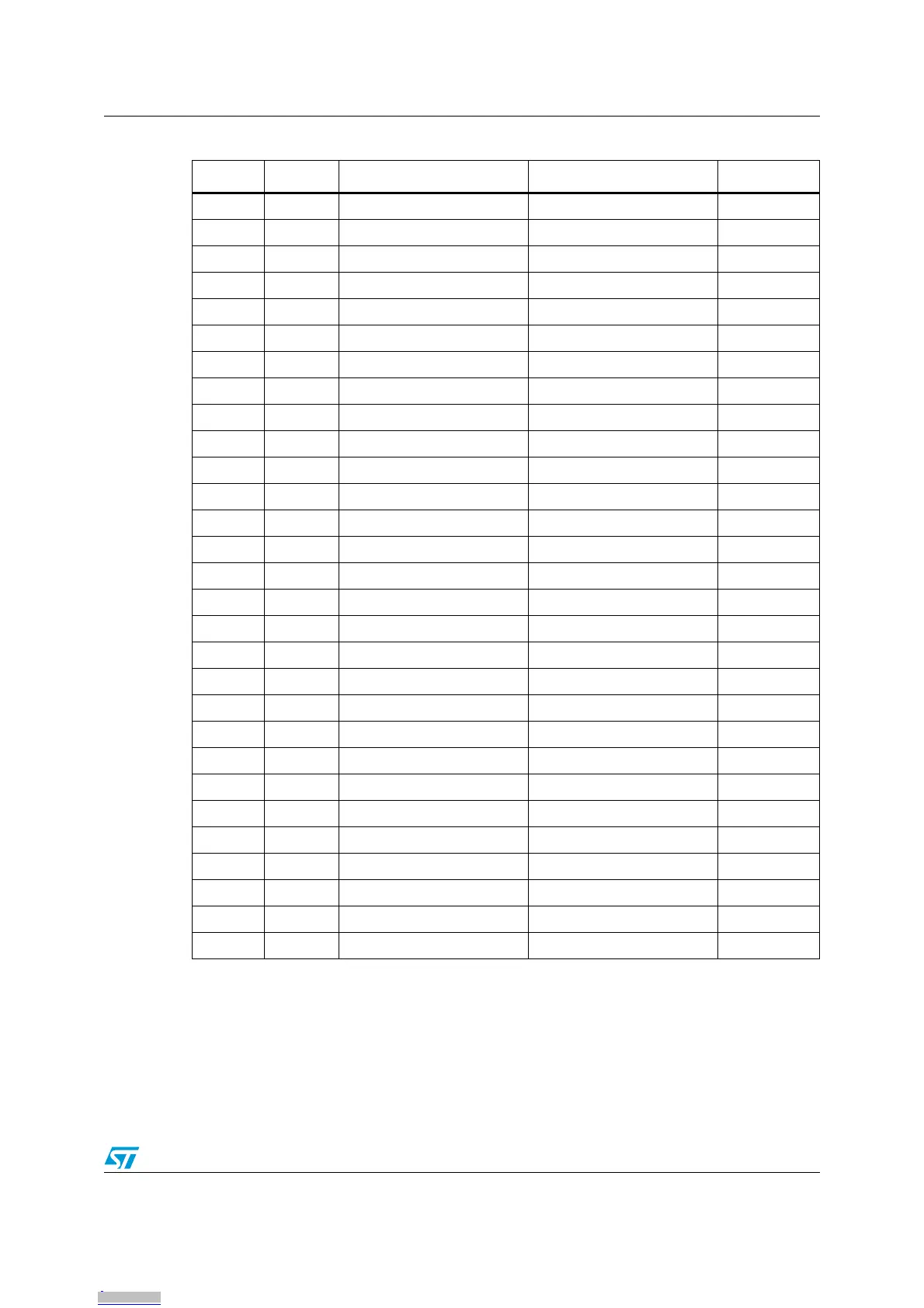
Note: Options are selected using 0-ohm resistors.
4VSS
5VCAP
6VDD
7VDDIO_1
8 PF4 Load
9VDDA
10 VSSA
11 PB5 LED2 I²C SDA R43
12 PB4 LED3 I²C SCL R42
13 PB3 Joy Down
14 PB2 Joy Left
15 PB1 Joy Right
16 PB0 Joy Up
17 PE5 LCD CS
18 PC1 Key K1
19 PC2 Key K2
20 PC3 Key K3
21 PC4 Buzzer Driven shield keys R4/R46
22 PC5 SPI SCK
23 PC6 SPI MOSI
24 PC7 Key K4
25 PD0 Key K5
26 PD1 DB SWIM connector MB SWIM connector W1
27 PD2 Slider S5
28 PD3 Slider S4
29 PD4 Slider S3
30 PD5 Slider S2
31 PD6 Slider S1
32 PD7 Driven shield slider LED1 R45/R44
Table 1. Daughterboard MCU pin description (continued)
Pin no. Pin name Application usage Option Configuration
Downloaded from Arrow.com.Downloaded from Arrow.com.Downloaded from Arrow.com.Downloaded from Arrow.com.Downloaded from Arrow.com.Downloaded from Arrow.com.Downloaded from Arrow.com.Downloaded from Arrow.com.Downloaded from Arrow.com.