7
Grounding/Bonding
Install, ground, bond and wire motor according to local or National Electrical
Code requirements.
Permanently ground motor. Use green ground terminal provided under motor
canopy or access plate (See Figure 3); use size and type wire required by
code. Connect motor ground terminal to electrical service ground.
Bond motor to pool structure. Use a solid copper conductor, size No. 8 AWG
(8.4 sq.mm) or larger. Run wire from external bonding lug (see Figure 3) to
reinforcing rod or mesh.
Connect a No. 8 AWG (8.4 sq.mm) solid copper bonding wire to the pressure
wire connector provided on the motor housing and to all metal parts of the
swimming pool, spa, or hot tub and to all electrical equipment, metal piping
or conduit within 5 feet (1.5 m) of the inside walls of swimming pool, spa, or
hot tub.
Wiring
Pump must be permanently connected to circuit. See Figures 4A and 4B for
wiring connection diagrams. Match wire and circuit breaker sizes to correct
Fusing and Wiring Data Chart (Page 8). If other lights or appliances are also on
the same circuit, be sure to add their amp loads to pump amp load. (If unsure
how to do this or if this is confusing, consult a licensed electrician.) Use the
load circuit breaker as the master on-off switch.
Install a Ground Fault Circuit Interrupter (GFCI) in circuit; it will sense a short-
circuit to ground and disconnect power before it becomes dangerous to pool
users. For size of GFCI required and test procedures for GFCI, see manufac-
turer’s instructions.
In case of power outage, check GFCI for tripping (which will prevent normal
water circulation). Reset if necessary.
NOTICE: If you do not use conduit when wiring motor, be sure to seal wire
opening on end of motor to prevent dirt, bugs, etc., from entering motor.
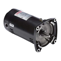
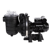
Figure 3: Typical ground screw and
bonding lug locations.
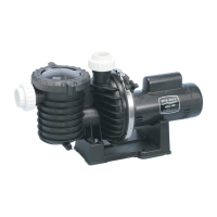
Figure 4A: Single-phase, single speed
wiring connection diagram.
For 3-phase connection, refer
to motor nameplate.
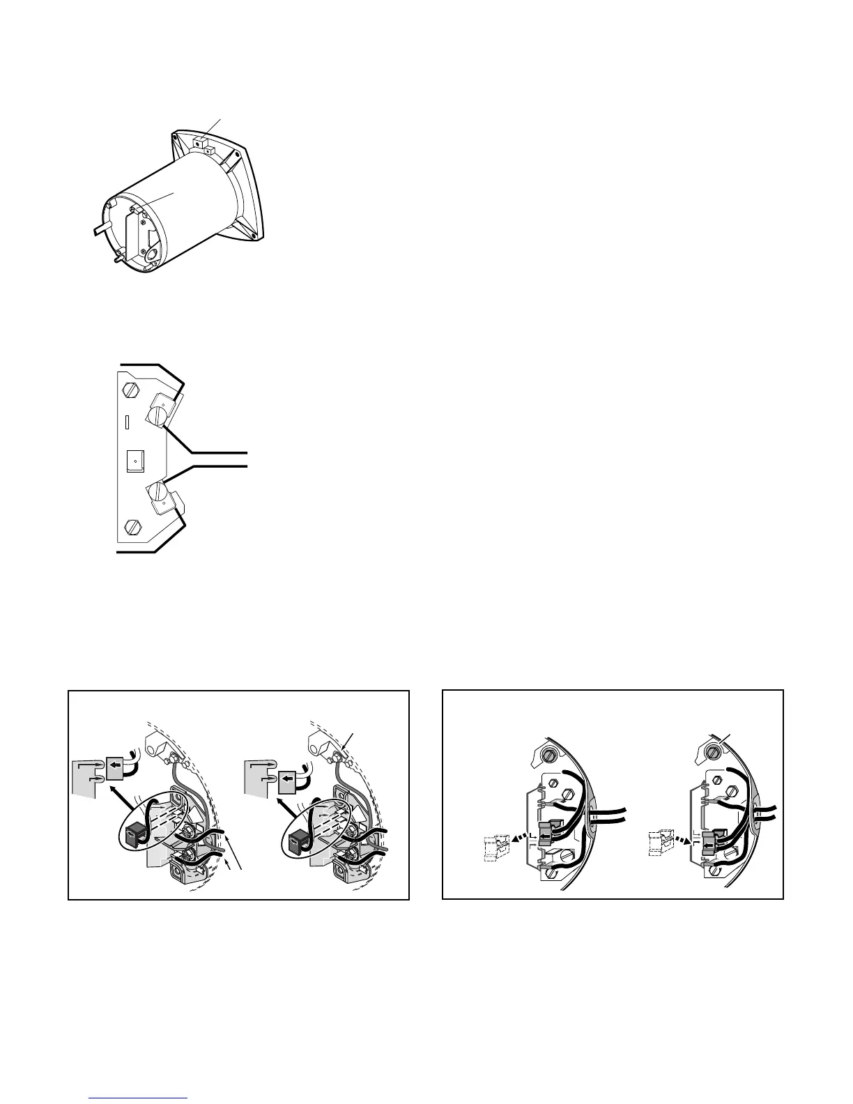
Figure 4B: Wiring connections for plug-in type terminal board (Single speed, single phase motors)
230 Volt to 115 Volt Conversion. Move plug to change voltage.
board.
1.
1.
2.
2.
'115 Volts'.
230 Volt to 115 Volt Conversion. Move plug to change voltage.