Component Replacement
2–16 Padlock Service Manual
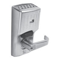
4. Press in on the disassembly tool and turn it counterclockwise until it
is engaged between the locking cam assembly and the spring
positioner, as shown in Figure 2.12. Gently pull the tool to remove
the locking cam assembly from the core receptacle.
5. Remove the shackle, shackle spring, and tumblers.
Assembling the
11B, 21B, 21JB,
and 41B
Padlocks
To assemble the 11B, 21B, 21JB, and 41B Padlocks, perform the
following steps:
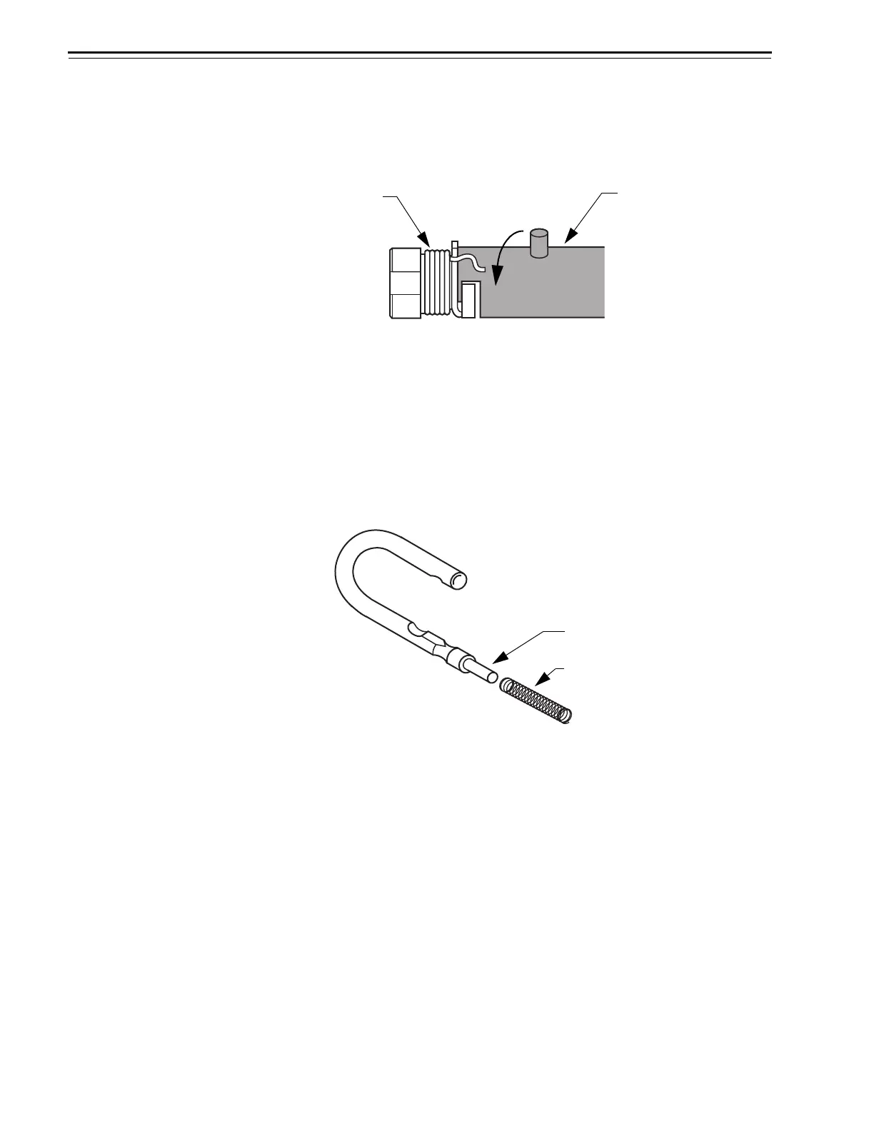
1. Place the shackle spring on the shackle spring post, as shown in
Figure 2.13.
2. Insert the long shackle leg and shackle spring into the long shackle
hole, and the short shackle leg into the short shackle hole. Hold the
shackle in the locked position.
Figure 2.12 Engaging and rotating the disassembly tool
Disassembly tool
Locking cam
assembly
Figure 2.13 Placing the shackle spring
Shackle spring post
Shackle spring
 Loading...