Component Replacement
Padlock Service Manual 2–17
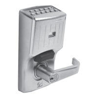
3. Turn the case upside-down. Drop the tumblers into the core
receptacle and push the tumblers into the case cross holes, as
shown in Figure 2.14.
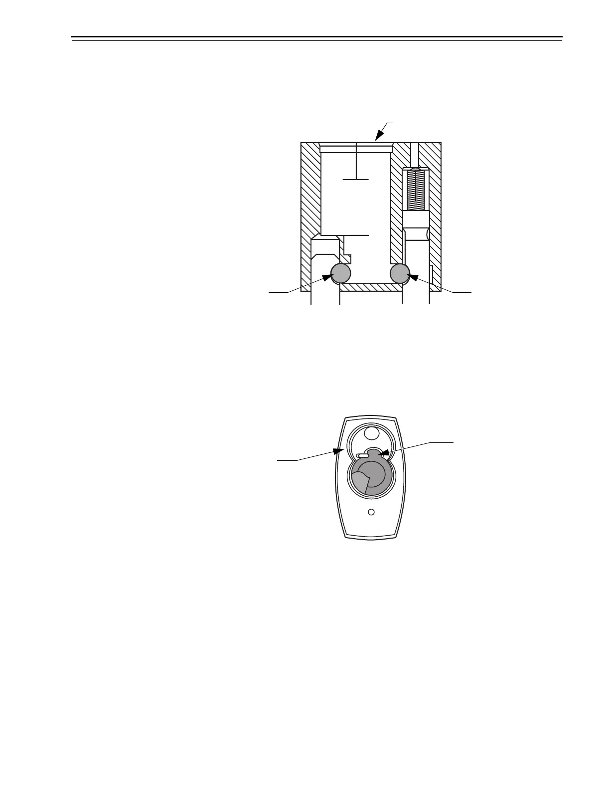
4. Insert the locking cam into the bottom core receptacle lobe so that
the round tip of the spring positioner is pointed toward the top core
receptacle lobe, as shown in Figure 2.15.
Figure 2.14 Pushing the tumblers into position (side, cross–section view)
Tumbler in
case cross hole
Tumbler in
case cross hole
Core receptacle
Figure 2.15 Inserting the locking cam (bottom view)
Round tip of the
spring positioner
Top core
receptacle lobe
 Loading...