Component Replacement
2–18 Padlock Service Manual
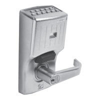
5. Using a punch or screwdriver, push on the round tip of the spring
positioner until the locking cam snaps clockwise into the slot, as
shown in Figure 2.16.
Caution
If the locking cam doesn’t seat fully, the tumblers may have rolled out
of position. Remove the locking cam and reposition the tumblers
before continuing.
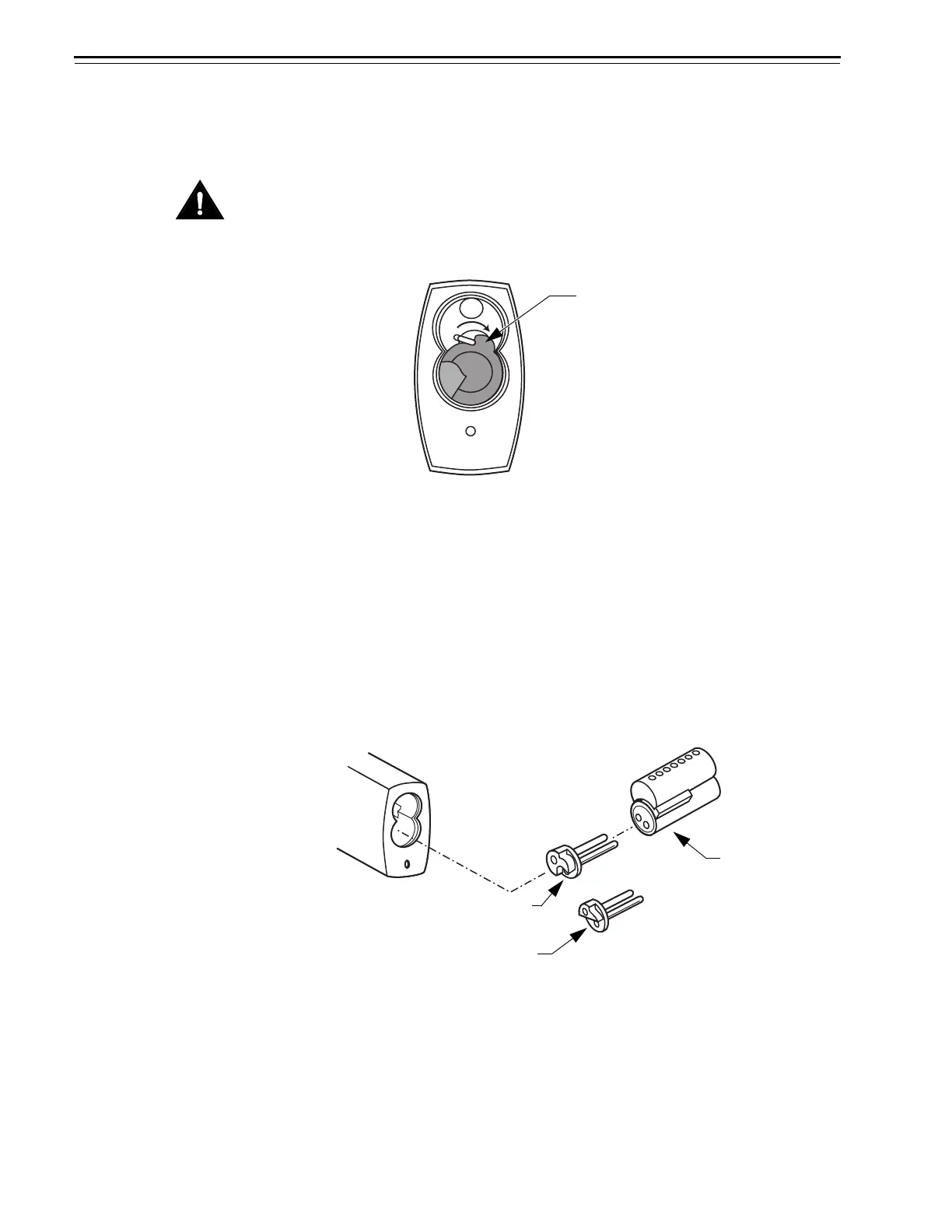
6. With the throw member’s recess on the same side as the core lug,
insert the throw member into the core, as shown in Figure 2.17.
With the control key in the core, insert the core with the throw
member into the core hole. Turn the control key to the left and
remove it.
Note: If the throw member is not installed properly, the core cannot
be installed.
7. If there is a dust cover assembly for the lock, position the dust cover
so that the lip faces upwards. Position the rubber seal under the
dust cover and push the button on the rubber seal through the
opening in the dust cover.
Figure 2.16 Pushing the locking cam into position (bottom view)
Round tip of the
spring positioner
Figure 2.17 Installing the core and throw member
Core lug
Recess on the non-key
retained throw member
Recess on the key
retained throw member
 Loading...