EX5500 Controller Installation & Configuration Guide
10
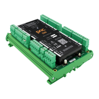
− (#i) 12 IN: Power connection accepts 12V Direct Current
− (#j) KEY1: Weigand Keypad connection
− (#k) KEY LED: Connects to Keypad LED
− (#l) DC OUT: Direct Current Power out
− (#m) KEY0: Weigand Keypad connection
− (#n) GND: Ground/Earth
− (#o) DOOR IN: Door switch connection
Note
Connect to COM and NO if you want the switched circuit to be on when
the relay is on.
Connect to COM and NC if you want the switched circuit to be on when
the relay is off.
Network and Power Connections to EX5500
The following is a brief summary of available powering and networking options:
Usage Option Description
Single EX5500 – not
connected to a
network
EX5500s can be used as standalone devices that function
independently without any network connection. In this
case, you only need to connect the EX5500 to the power
supply.
Using System Manager, set the device as “not connected to
the network."
Single EX5500 –
connected to a
network
EX5500s can be remotely controlled (for configuration and
monitoring purposes) via the local area network. In this
case, you need to connect it to both a power source and the
network.
EX5500s also support power-over-Ethernet (PoE), which
supplies both power and network services via a single
connection.