FIG,
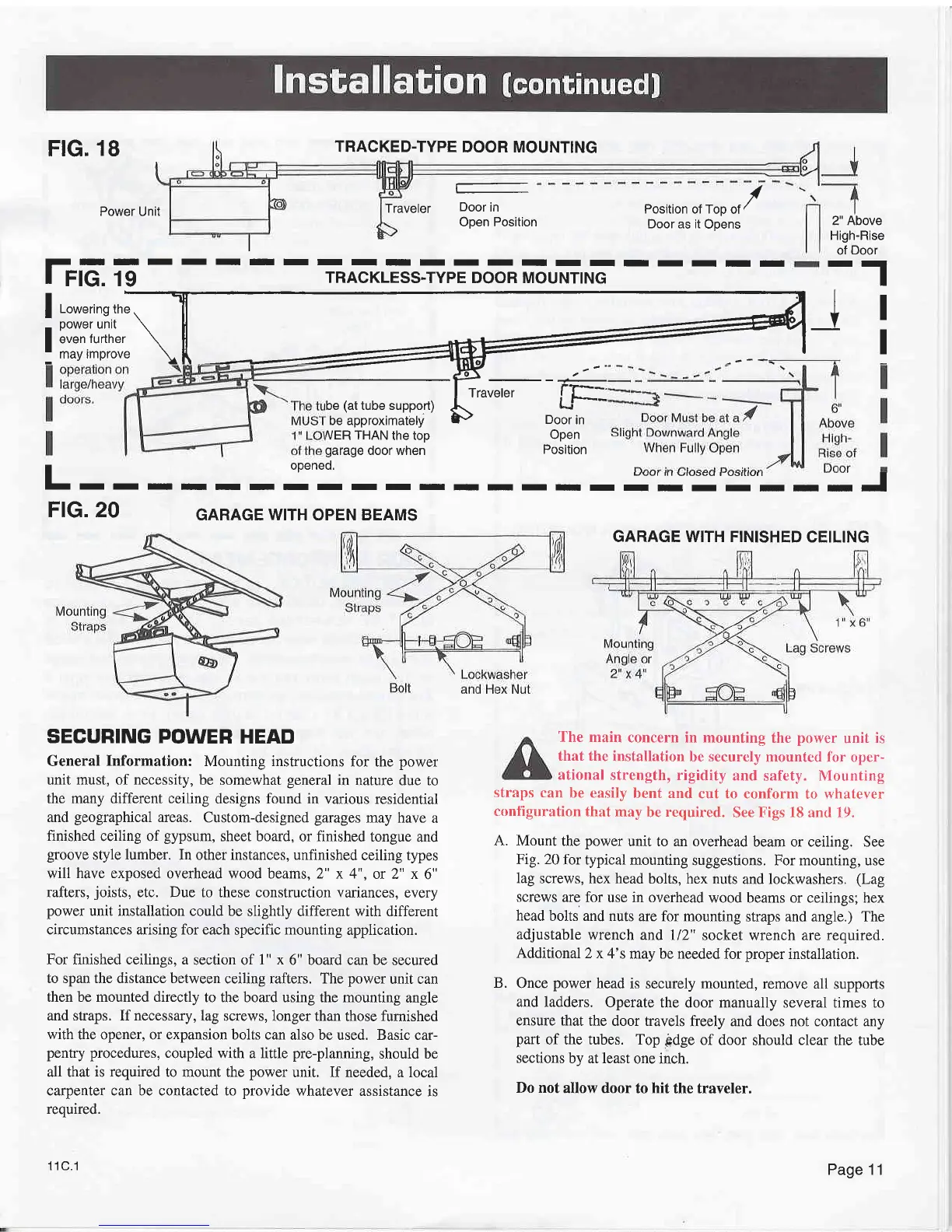
18
TRACKED.TYPE
DOOR MOUNTING
Traveler
Door
in
Open Position
Door as it
Opens
IIIIIIIIIIIIII
TRACKLESS-TYPE
DOOR MOUNTING
SEGURING
POWER HEAD
General
Information:
Mounting instructions
for the
power
unit must, of necessity,
be somewhat
general
in
nature due to
the many different ceiling
designs found in
various residential
and
geographical
areas.
Custom-designed
garages
may have
a
finished
ceiling of
gypsum,
sheet board,
or
finished
tongue
and
groove
style
lumber.
In other instances, unfinished
ceiling types
will
have exposed
overhead wood beams, 2" x 4",
or 2" x
6"
rafters,
joists,
etc. Due to these construction variances,
every
power
unit installation could be
slightly different with different
circumstances arising for each
specific
mounting
application.
For finished ceilings, a
section of
1" x
6" board can be
secured
to span the distance between
ceiling rafters. The
power
unit can
then be mounted directly
to the board using the mounting
angle
and straps. Ifnecessary,
lag screws, longer than
those
furnished
with
the opener, or expansion bolts can
also be used. Basic car-
pentry procedures,
coupled
with a little
pre-planning,
should be
all that
is required
to mount the
power
unit. If needed, a local
carpenter can be contacted to
provide
whatever assistance
is
required.
11C.1
/
Position of Top
of
/
2" Above
High-Rise
of
Door
--r
The main
concern
in mounting the
power
unit
is
that the
installation
be securely
mounted for oper-
ational
strength, rigidity
and
safety.
Mounting
straps can
be easily
bent and
cut to conform
to
ryhatever
conliguration
that
may
be
required.
See Figs
18
and
19.
A. Mount
the
power
unit to an overhead
beam or ceiling. See
Fig.20
for typical
mounting
suggestions. For mounting, use
lag
screws, hex
head bolts, hex
nuts and lockwashers.
(Lag
screws
are for
use in overhead
wood beams or ceilings; hex
head
bolts and
nuts are for mounting
straps and angle.) The
adjustable
wrench and ll2"
socket wrench are required.
Additional
2
x 4's may be needed
for
proper
installation.
B.
Once
power
head is
securely mounted, remove all
supports
and ladders.
Operate
the door manually several
times to
ensure that
the door travels
freely and does not contact any
part
of the tubes. Top
pdge
of door
should
clear
the tube
sections
by at least
one inch.
Do not
allow door
to hit the traveler.
Power Unit
IIIIIIIII
I
Ftc. 19
rlr
f
Lowerinsthe,
\ 4 J I
]oo*urrn,.
\
ll
El
v
:
li:?,Hl11
\[ _
-l-
l
be
(at
tube support)
Ll
raveler
LF---
be approximately
P
Door
in
J€<
l=^
-^'
. I
rrav
be
1ar
tuoe suppon)
a\
Ll---
be approximately
P
Door
in
MER THAN
the top
OPen
garage
door when
Position
I
openeo.
I
openeo.
I- - r
r r r r r r r r r
r - r
r -;"5'=':-:
- - J
FrG. 20
GARAGE WITH OPEN BEAMS
GARAGE WITH FINISHED
CEILING
Page 1 1