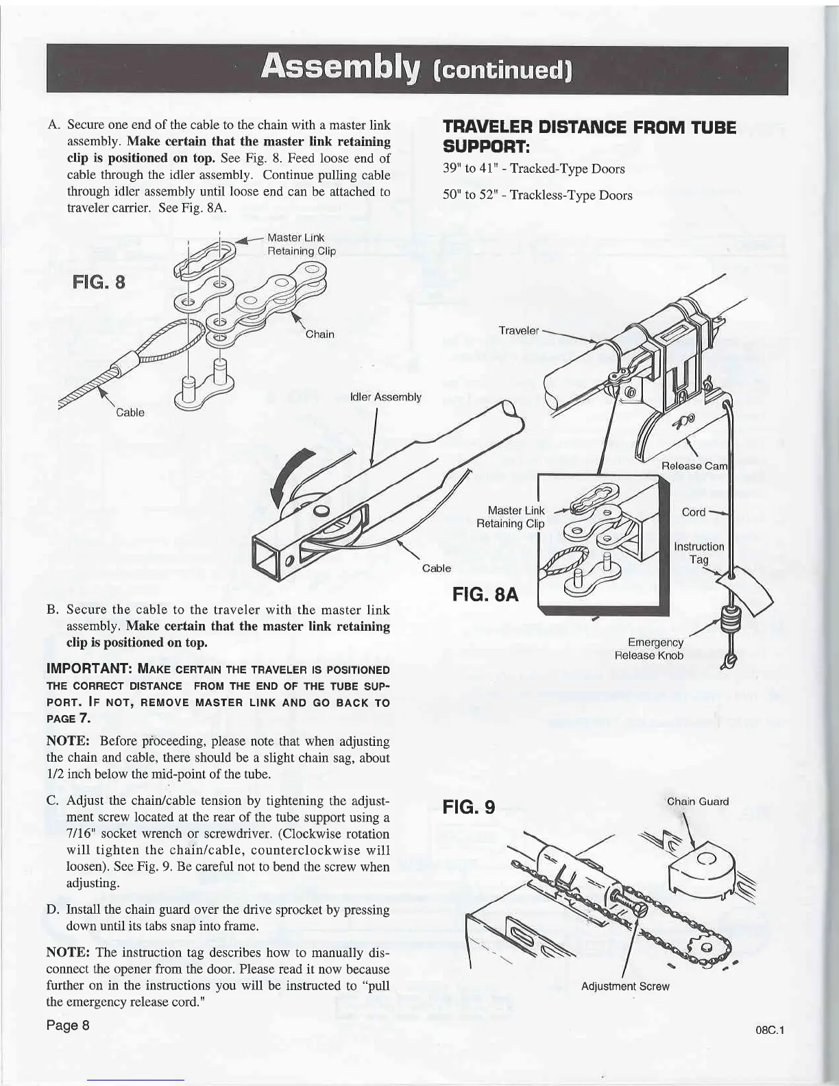
A. Secure one end
of the cable to the chain with a master
link
assembly. Make
certain that the master link retaining
clip is
positioned
on top. See
Fig.
8. Feed loose
end of
cable through the idler
assembly. Continue
pulling
cable
through idler
assembly until
loose
end can be attached
to
traveler carrier.
See
Fis.
8A.
TRAVELER
DISTANCE
FROM
TUBE
SUPPORT:
39" to 41u
-
Tracked-Type
Doors
50"
to 52"
-
Trackless-Type
Doors
B.
Secure the cable to the
traveler with the master
link
assembly. Make certain that the
master
link
retaining
clip is
positioned
on top.
IMPORTANT: MnrE
cERrAtN THE TRAVELER ts
postnoNED
THE CORRECT DISTANCE FROM THE END
OF THE TUBE
SUP.
PORT, lF NOT, REMOVE MASTER L|NK
AND GO BACK
TO
PAGE 7.
NOTE:
Before
pioceeding, please
note that when
adjusting
the chain
and cable, there should be a slight
chain sag, about
l/2
inch below the mid-point of the tube.
C. Adjust the chain/cable tension by
tightening the
adjust-
ment screw located
at
the rear
of the tube support
using a
7/16"
socket wrench or screwdriver.
(Clockwise
rotation
will tighten the chain/cable,
counterclockwise
will
loosen).
See
Fig.
9.
Be
careful
not
to bend the
screw when
adjusting.
D.
Install the chain
guard
over the drive
sprocket by
pressing
down until its tabs
snap
into frame.
NOTE: The instruction
tag describes how to manually
dis-
connect the opener from
the door. Please read it now
because
further on in the instructions you
will be instructed
to
"pull
the emergency release
cord."
Page
8
FIG.
8A
FIG.
9
Adiustment
Screw
08c.1