IMPORTANT:
THe oooR opENER
pRovrDES
FoR
posrlvE
cLosrNG
oF THE
DooR. At-l
extsrtruc
DooR
LocKs MUST
BE MADE
tNopERnrtve. lr exlst-
ING
DOOR LOCKS
ARE LOCKED
WHILE
TRYING TO USE THE
OPENER,
DAMAGE
TO OPENER
AND DOOR
COULD RESULT.
Pin
or screw the
existing
lock mechanism
in the "open"
(unlocked)
position. If necessary,
the catch
latches may
be
Pin or Screw
in
Unlocked
Position
repositioned
or
the
complete
lock
assembly
Because
of the
many
styles of door
locks,
show only two of the more common types.
IMPORTANT:
lr
rs rruponrerur
AND CORDS, THAT COULD CAUSE
BE REMOVED FROM
THE DOOR.
_--
Remove
*'t
Lock Plates
-
may be removed.
the illustrations
THAT ALL ROPES
ENTANGI-EMENT,
Both Ends ol
Doors
FrG. 29
FrG.
30
35 Feet of Wrre
Red Alignment
Light
Your
garage
door opener
is supplied with an
infrared beam
sensor
that sends
an invisible beam
of light from the sending
unit to the
receiving unit across
the
pathway
of the
door.
Please read
and follow these
instructions carefully.
IMPORTANT:
THe
DooR
OPENER
WILL
NOT OPERATE
UNTIL
THE
BEAM SENSOR
IS
CONNECTED
TO THE
POWER UNIT
AND
PROPERLY
ALIGNED.
THe tnvtstare
eeau or
LIGHT
MUST NOT
BE OBSTRUCTED,
OTHERWISE,
THE
DOOR
CAN BE CLOSED
BY
MAINTAINING
CONSTANT
PBESSURE ON
THE
WALL-MOUNTED
PUSHBUTTON
ONLY.
THe rnnrusutrrER
cANNor
BE usED
To closE THE
ooon. Tue
DooR cAN.
BE opENED
uslNc
EITHER THE
HAND-HELD
TRANSMITTER
OR
WALL-MOUNTED
PUSHBUTTON
EVEN IF
THE BEAM
IS NOT ALIGNED OR
CONNECTED
TO THE POWER
UNIT.
PULL EMERGENCY
RELEASE CORD
TO DISCONNECT
DOOR
FROM OPENER,
THEN MANUALLY
CLOSE
GARAGE
DOOR BEFOHE
CONTINUING.
Before beginning
beam sensor
mounting, identify
which side of the
garage
door
opening
(if
any) the sun
is "likely" to shine
into. Since
sunlight
may cause
undesirable
operation,
you
should
plan
to mount the
small
sending unit
(not
the receiving
unit) on the side
of the door opening
exposed
to the sun.
Page 14
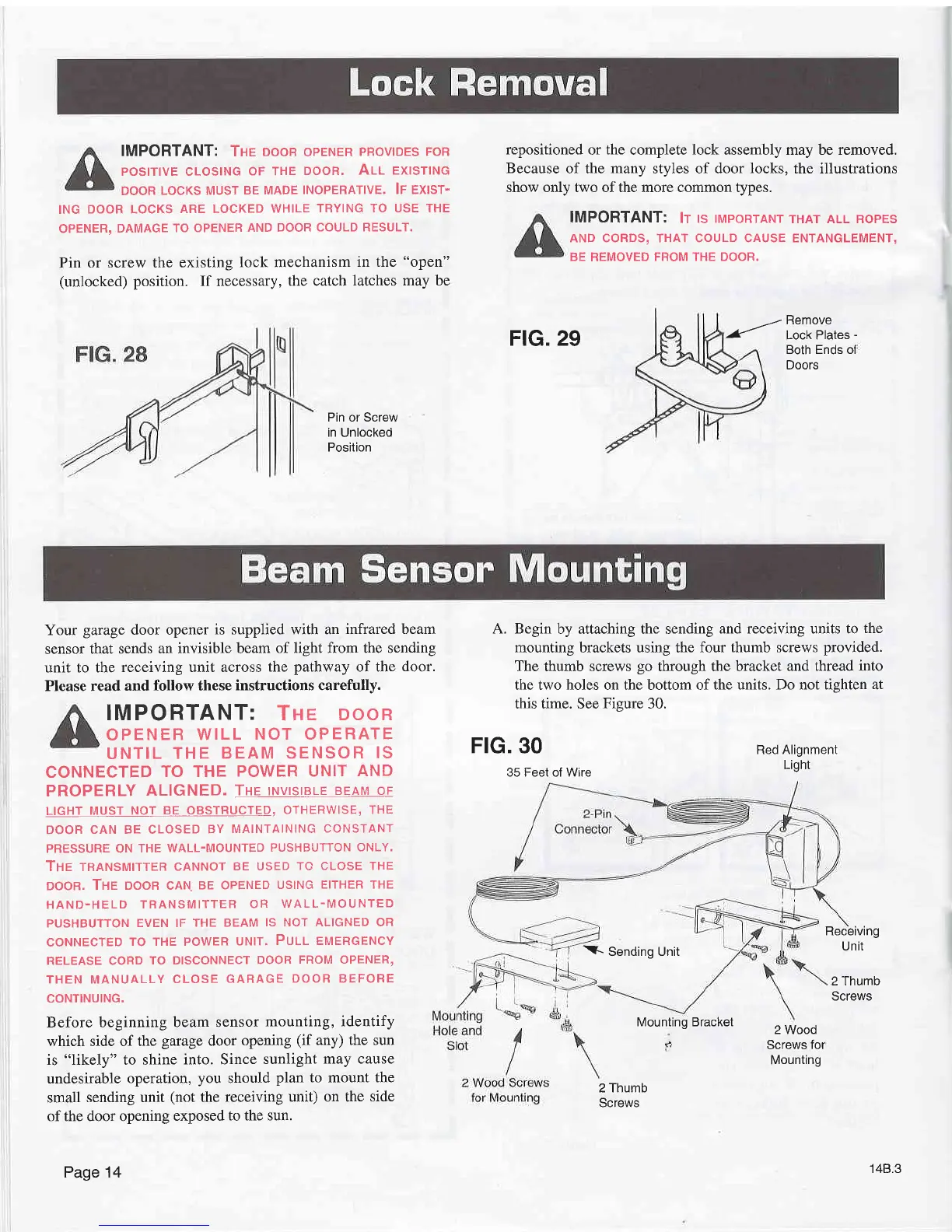
A. Begin
by attaching the sending
and receiving units to
the
mounting brackets using the
four thumb screws
provided.
The thumb screws
go
through the bracket
and thread into
the two holes on the bottom of
the units. Do not tishten at
this time. See
Figure
30.
*-Sending
Unit
Mounting Bracket
2 Thumb
Screws
Receiving
Unit
2 Thumb
Screws
2 Wood
Screws
for
Mounting
148.3