B.
C.
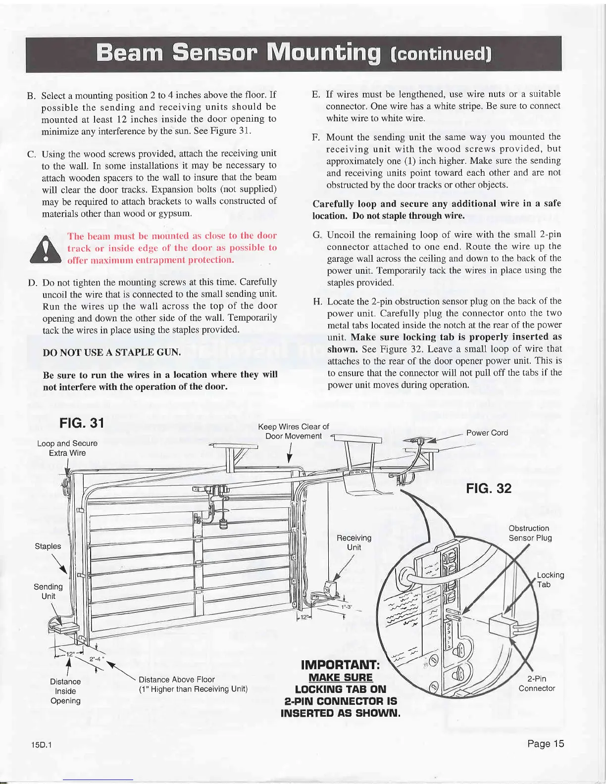
Select
a
mounting
position 2
to
4 inches above
the
floor. If
possible
the
sending
and receiving
units
should
be
mounted
at least
12 inches
inside the
door opening
to
minimize
any
interference
by the sun.
See Figure
31'
Using
the wood screws
provided,
attach
the
receiving unit
to the
wall. In some
installations
it may be
necessary to
attach
wooden
spacers
to the
wall to insure
that
the beam
will clear
the door
tracks.
Expansion
bolts
(not
supplied)
may be
required to attach
brackets
to
walls constructed
of
materials
other
than wood
or
gypsum.
The beam
must
be mounted
as close to the
door
track
or inside
edge
ol' thc door
as
possible
to
of'f'er
maximum
entrapment
protection.
Do not tighten
the
mounting screws
at this
time. Carefully
uncoil
the wire
that is connected
to
the small sending
unit.
Run
the wires
up the wall
across
the top
of the door
opening
and
down the
other side
of the wall.
Temporarily
tack
the wires
in
place
using the staples
provided.
DO NOT USE
A STAPLE
GUN.
Be sure
to run
the wires
in a location where
they will
not
interfere with
the operation
of the
door.
FIG, 31
Loop and Secure
Extra Wire
E. If wires must be
lengthened, use wire
nuts or a suitable
connector. One wire has a
white stripe.
Be sure to connect
white wire
to white wire.
F.
Mount
the
sending unit the same
way
you
mounted
the
receiving
unit with the wood
screws
provided,
but
approximately
one
(1)
inch higher.
Make sure
the sending
and receiving
units
point
toward
each other
and are
not
obstructed by the
door tracks or other
objects.
Carefully
loop and secur€
any additional
wire
in a safe
location. Do
not
staple
through wire.
Uncoil the remaining
loop of wire with
the small
2-pin
connector attached to one
end. Route
the wire
up the
garage
wall across the
ceiling and down
to the
back of
the
power
unit. Temporarily
tack the wires
in
place using the
staples
provided.
Locate the 2-pin obstruction
sensor
plug
on
the back
of the
power
unit. Carefully
plug
the connector
onto
the two
metal tabs located inside the
notch at the
rear of the
porver
unit. Make sure locking
tab is
properly
inserted
as
shown. See
Figure 32. Leave
a small loop
of
wire that
attaches to
the rear of the door opener
power unit. This
is
to ensure that the connector will
not
pull
off
the tabs
if the
power
unit moves during operation.
D.
G.
H.
Keep
Wires Clear of
Door
Movement
I
V
Power Cord
FlG. 32
Obstruction
Sensor
Plug
apres
\
SI
Receiving
Unit
IMPORTANT:
MAKE
SURE
LOCKING
TAB ON
z.PIN CONNECTOR
IS
INSERTED
AS SHOWN.
Locking
Tab
Sending
Unit
-
lX..r.-
/
r-
\
Distance
\
Distance
Above Floor
)rt"t
lnside
Opening
2-Pin
Connector
---'€;
ffi
\*>
15D.1
(1"
Higher
than Receivlng Unit)
Page
15