To neoucE THE RtsK
oF ELEcrRlc sHocK, coNNEcr
rHE
powER
coRD
oNLy ro
A
pRopERLy
cRouNDEo 3
pnoHc
120
voLT
ourLET.
Do
ruor
usE AN EXTENSIoN coRD oR cHANGE
THE
pLUG
rN ANy wav. lr rHE
pLUG
ooEs
Nor
Flr tNTo rHE
OUTLET, CONTACT
A OUALIFIED
ELECTRICIAN TO INSTALL THE
pRopER
ourLET.
As
soon
As
powER
ts AppLrED To rHE uNrr,
TIIE LIGHT ON THE
OPENER
SHOULD
BLINK
ONCE.
PERMANENT WIRING
INSTRUCTIONS
I \ DtscotrxEcr
powER
Ar FUsE Box BEFoRE
Il
PRooEEDTNG.
NOTE:
Where required by local codes, opener
must
be
per-
manently
wired.
Services of a
licensed electrician can be
obtained
to
perform
the
above
permanent
wiring.
n WARNI
NG I Bepone coNNEcrNG
II
POWER, PLEASE
REVIEW THESE IMPORTANT
SAFETY
lNsrRUcloNS.
THEy ARE DESIcNED
To REDUcE THE
RlsK oF sEVERE tNJURy oR
DEATH. PlEase READ AND
FoL-
LOW ALL INSTRUCTIONS
CAREFULLY.
A.
Neven LET cHILDREN opERATE,
oR
pLAy
wtrH DooR coN-
TRoLS. Keep neuorE coNTRoL
AWAv FRoM oHILDREN.
B. Alwavs KEEp
MovrNG DooR
tN
stcHT
AND AwAy FRoM
PEOPLE AND OBJECTS UNTIL
IT IS COMPLETELY CLOSED.
NO ONE SHOULD
CROSS
THE PATH
OF
THE
MOVING
DOOR.
C. Tesr
DooR opENER
MoNrHLy. TnE caRace
ooon
MUST
REVERsE oN coNTAcr
wrrH A 1-112 tncn oBJEcr
(on
n 2
x 4 eoano
laro runr) oN THE FLooR.
lr aoJusrtnc
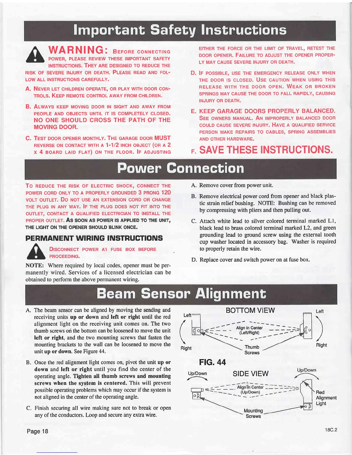
A.
The beam sensor can
be
aligned
by moving the sending and
receiving units up
or down and left
or right
until the
red
alignment
light
on
the
receiving
unit
comes on. The two
thumb
screws od the bottom
can
be
loosened to move the unit
left
or
right, and the two
mounting screws that fasten the
mounting brackets to the
wall
can
be loosened to move the
unit up or down. See
Figure 44.
B. Once the
red alignment light comes
on,
pivot
the unit up or
down and
left or right until
you
find
the
center of the
operating angle. Tighten
all thumb screws and
mounting
screws
when
the system
is centered.
This will
prevent
possible
operating
problems which may occur if the system is
not
aligned
in the
center
of the
operating angle.
C.
Finish securing all
wire making
sure not to break or open
any of
the conductors. Loop
and secure any extra
wire.
EITHER THE FORCE OR THE
LIMIT
OF
TRAVEL,
RETEST THE
DooR
opENER.
FltluRE To ADJUST
THE oPENER
PRoPER-
LY MAY CAUSE
SEVERE INJURY OR
DEATH.
D. lr
possteLE,
usE THE
EMERGENcv
RELEASE
oNLY
wHEN
THE
DooR ls
cLosED.
Use cauloN
wHEN
ustNc THls
RELEAsE
wrrH THE DooR
opEN. Weer oR
BRoKEN
SPRINGS MAY
CAUSE THE
DOOR TO FALL
RAPIDLY, CAUSING
INJURY OR
DEATH.
E. KEEP GARAGE
DOORS PROPERLY
BALANCED.
See
owruens
MANUAL. Ar tmpnopERLy
BALANoED
DooR
couLD cAUSE
sEvERE tNJURy. Have
n
QUALIFIED
sERvlcE
PERSON
MAKE REPAIRS TO
CABLES, SPRING
ASSEMBLIES
AND OTHER
HARDWARE.
F.
SAVE
THESE INSTRUCTIONS.
Remove cover from
power
unit.
Remove electrical
power
cord
from opener and
black
plas-
tic
strain relief bushing. NOTE:
Bushing can be
removed
by compressing with
pliers
and then
pulling
out.
Attach
white
lead to silver colored
terminal
marked Ll,
black
lead
to brass colored terminal
marked
L2, and
green
grounding
lead
to
ground
screw using the
external
tooth
cup
washer located in accessory bag.
Washer
is required
to
properly
retain the
wire.
Replace
cover and switch
power
on at fuse box.
A.
B.
C.
Left
I
Righl
Lett
/
(
Right
D.
FlG. 44
Up/Down
BOTTOM VIEW
Thumb
Screws
SIDE
VIEW
Mounting
Screws
Red
Alignment
Light
Page 18
18C.2