– 27 –
Modular plug
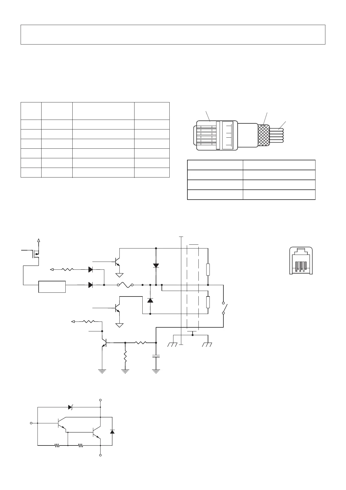
Pin No.
Signal
Function
I/O
name direction
1 FG Frame ground —
2 DRD1 Drive signal 1 OUT
3 +24 V Drive power OUT
4 +24 V Drive power OUT
5 DRD2 Drive signal 2 OUT
6 DRSNS Sense signal IN
9. Peripheral Unit Drive Circuit
Peripheral unit drive circuit connector only connects to peripheral units such as cash drawers, etc.
Do not connect it to a telephone.
Use cables which meet the following specications.
Peripheral Drive Connector
Note: Connect a shielded wire to pin 1
(frame ground).
Modular jack plug
Shield
Wire lead
Manufacturer Model
MOLEX 90075-0007
AMP 641337
FCI B-66-4
6 1
6-pin modular
jack connector
Frame
FG
2
3
4
5
6
1
VCC
+24V
M-GND
M-GND
VCC
SX34SX34
33k33k
SS14SS14
10k10k
GS1DGS1D
2SD18662SD1866
78247824
VIN
1
VOUT
3
GS1DGS1D
2SD18662SD1866
FUSE 2AFUSE 2A
L1L1
Q4Q4
C3875C3875
4.7k4.7k
10k10k
0.022u0.022u
L2L2
Compulsion switch
6P Modular
Peripheral unit 2
Shielded cable
Peripheral unit 1
Drive Output:24 V, Max. 1.0 A
Drive circuit
e recommended drive unit is shown below.
E
C
R3 R4
R3
=
3.5KΩ
R4
=
300Ω
B
Reference
2SD 1866 Circuit Conguration

 Loading...