30
Installation
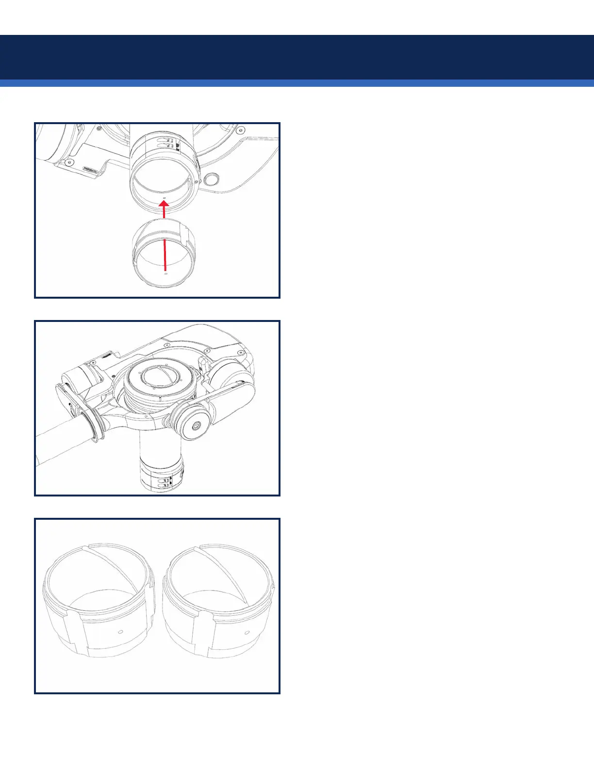
Next, add the lower post insert.
There is a locating pin inside the gimbal which
must be indexed with the hole in the insert.
For 1.5” and 1.58” posts, the shorter ange
is oriented UP, so the insert is ush with the
bottom of the gimbal when installed.
The insert should *click* into place.
Test t the gimbal onto the post.
Test the gimbal clamping ability across the
entire usable area of the post. The low-prole
clamp is easy to use and offers a positive lock.
NOTE: Some posts are slightly wider at the
top, so the gimbal might be snug at rst, then
looser once it’s past the top. Be gentle.
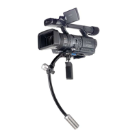
Some adjustment to the spacer thickness may
be required, using ne sandpaper.
Remove the spacers from the gimbal, sand a
small amount evenly around the inside of the
spacer, clean off any dust, and reinstall to test
the t.