Panel Controls for the Software Programs
UR28M Operation Manual 21
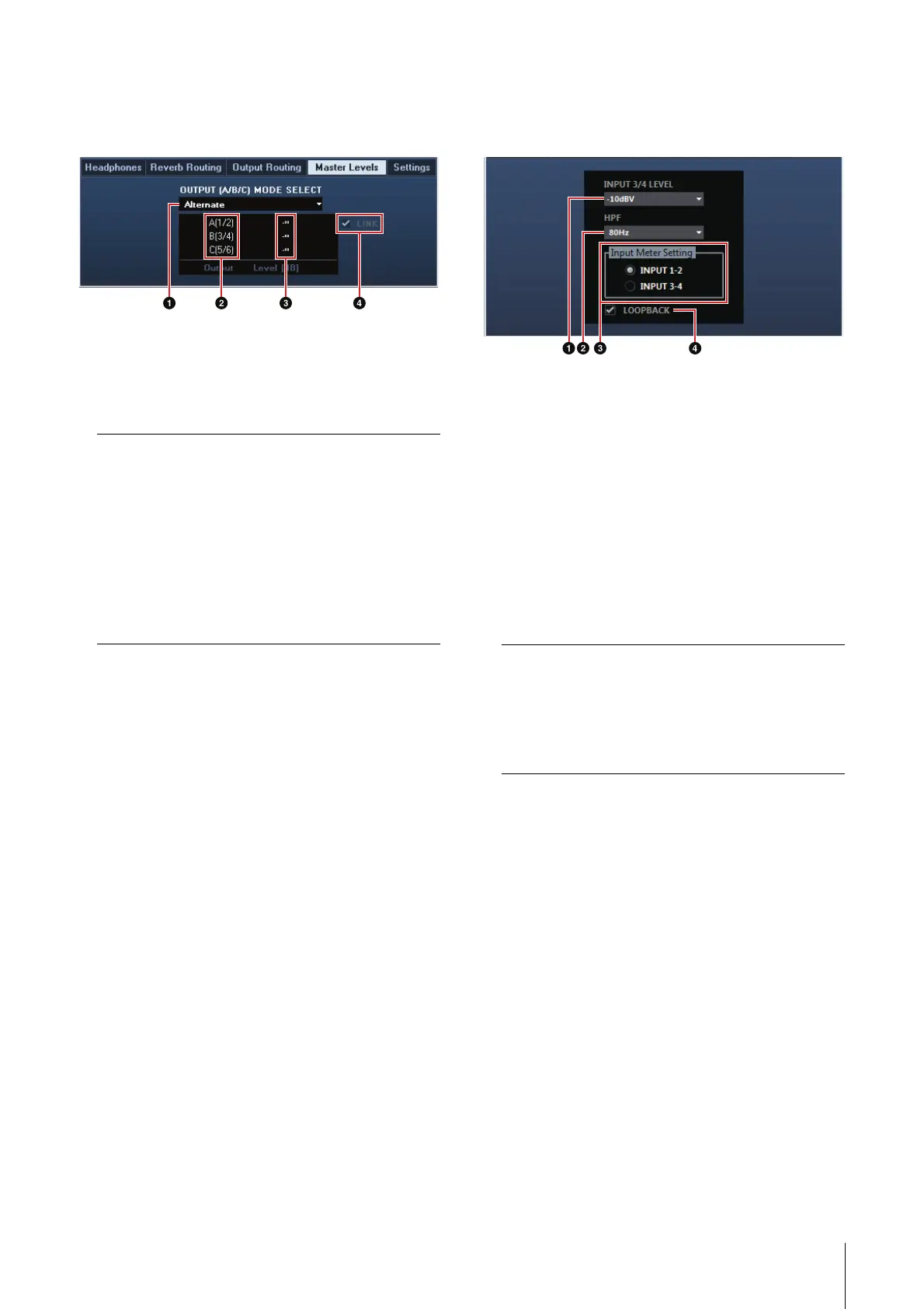
Master Levels Window
This is the window for configuring the master level of
the output jacks on the device.
1 OUTPUT (A/B/C) MODE SELECT
Selects the function (mode) of the LINE OUTPUT
A–C.
There are two modes, Alternate and Independent.
2 Master Source
Indicates the LINE OUTPUT.
3 Master Level
Indicates the output signal level of the LINE
OUTPUT.
4 LINK (Independent mode only)
Lets you enable (checkmark) or disable (no
checkmark) the function which adjusts the level of
all LINE OUTPUT signals by the OUTPUT LEVEL
knob on the device at the same time.
For instructions on how to adjust the output signal
level with LINK disabled, refer to the “OUTPUT
LEVEL knob” (page 9) in the section “Panel
Controls and Terminals (Details).”
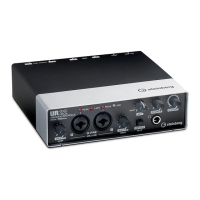
Settings Window
This is the window for configuring the device
settings.
1 INPUT 3/4 LEVEL
Selects the input signal level of LINE INPUT 3/4.
Option: +4dBu, -10dBV
2 HPF
Selects the cutoff frequency of the high pass filter.
Option: 120 Hz, 100 Hz, 80 Hz, 60 Hz, 40 Hz
3 Input Meter Setting
Selects the analog input jacks whose input signal
levels are indicated on the INPUT meter on the
device.
4 LOOPBACK
Turns the Loopback function on (lit) and off
(dark). Refer to the “LOOPBACK” in the section
“dspMixFx UR28M” (page 17).
Mode Description
Alternate One of the LINE OUTPUTS A–C
selected by the OUTPUT buttons
A–C outputs a single MIX signal
selected by the SOURCE SELECT
button.
Independent The LINE OUTPUTS A–C output
each MIX selected by the SOURCE
SELECT button at the same time.
Option Description
INPUT 1-2 Indicates the input signals of MIC/
LINE/HI-Z 1/2.
INPUT 3-4 Indicates the input signals of LINE
INPUT 3/4.