Chapter 3 - Maintenance
3-5
Holding Valve Inspection Procedure
The cylinders are equipped with holding
valves that prevent sudden movement of the
cylinder rods in the event of a hydraulic hose
or hydraulic component failure. The valve is
checked in the following manner:
1. Identify the cylinder in question.
2. Identify the holding valves and the cylinder
direction in question.
a. Cylinder Extend.
b. Cylinder Retract.
3. Place the machine so that the cylinder will
be located in the appropriate testing
position.
4. Pick the load (Do not exceed capacity, rated
or stability).
5. Disengage hydraulics.
6. Operate crane functions.
A. If the cylinder creeps (lowering the
load), replace the holding valve.
B. If the cylinder does not creep (load
stays suspended), the valve is
operational.
Gear-Bearing Bolt Maintenance
Anytime a gear-bearing bolt is removed, it
must be replaced with a new bolt of the
identical grade and size. Once a bolt has
been torqued to 75% of its proof load and then
removed, the torque coefficient may no longer
be the same as when the bolt was new thus
giving indeterminate damp loads after
torquing.
Warning!
Failure to replace gear-bearing
bolts may result in bolt failure
due to metal fatigue causing
serious injury or even death.
When using the torque data in the charts
above, the following rules should be observed.
1. Bolt manufacturer’s particular specifications
should be consulted when provided.
2. Flat washers of equal strength must be used.
3. All torque measurements are given in
foot-pounds. To convert to inch-pounds,
multiply by 12.
4. Torque values specified are for bolts with
residual oils or no special lubricants applied.
If special lubricants of high stress ability,
such as Never-Seez compound graphite and
oil, molybdenum disulphite, colloidal copper
or white lead are applied, multiply the torque
values in the charts by the factor .90. The
use of Loctite does not affect the torque
values listed above.
5. Torque values for socket-head capscrews
are the same as for Grade 8 capscrews.
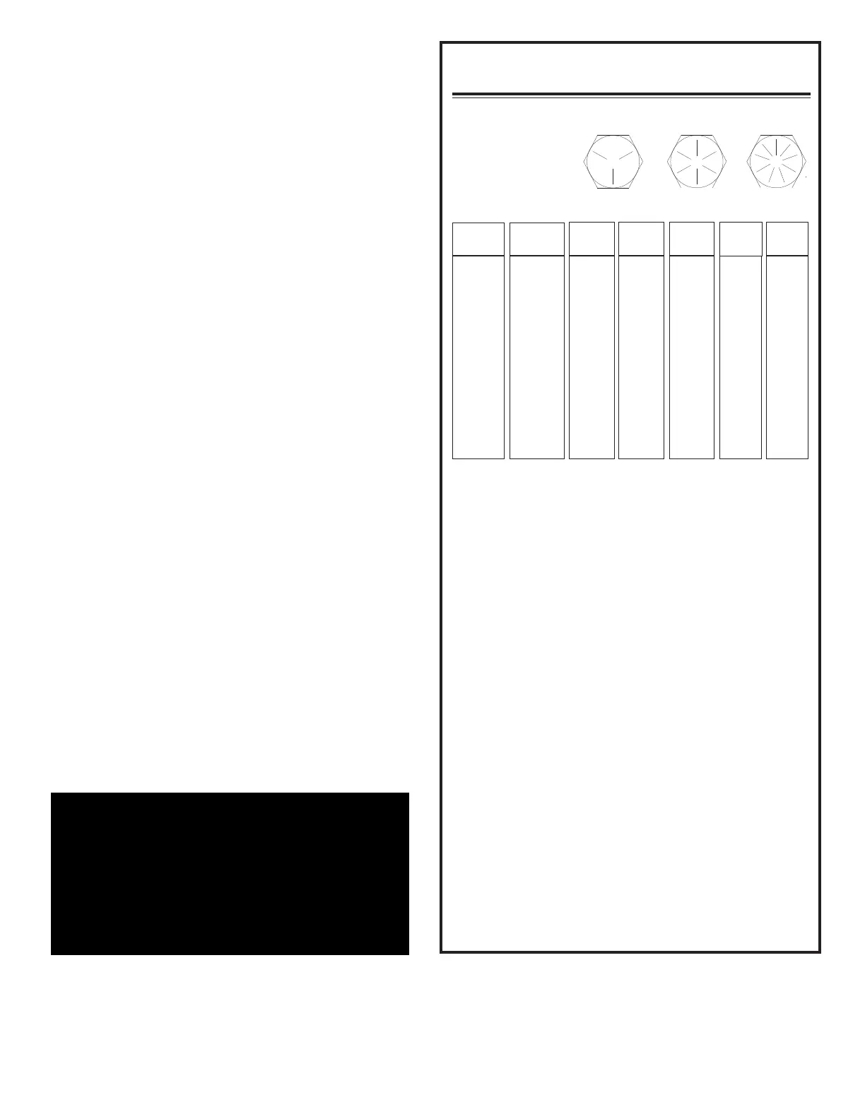
Torque Data Chart
22
39
63
96
139
192
340
549
823
1167
1646
2158
2865
18
33
52
80
115
160
280
455
680
965
1360
1780
2370
Plated
(Ft-Lb)
Plated
(Ft-Lb)
25
44
70
105
155
220
375
605
910
1290
1815
2380
3160
Plain
(Ft-Lb)
13
23
37
57
82
115
200
295
445
595
840
110
1460
Plated
(Ft-Lb)
17
31
49
75
110
150
265
395
590
795
1120
1470
1950
Plain
(Ft-Lb)
0.3125
0.3750
0.4375
0.5000
0.5625
0.6250
0.7500
0.8750
1.000
1.1250
1.2500
1.3750
1.500
Bolt DIA
(Inches)
5/16-18
3/8-16
7/16-14
1/2-13
9/16-12
5/8-11
3/4-10
7/8-9
1-8
1 1/8-7
1 1/4-7
1 3/8-6
1 1/2-6
Size
(DIA-TPI)
Grade 5
Grade 8
Grade 9