Instruction Manual
for
AS380 Series Elevator Integrated Drive Controller
108
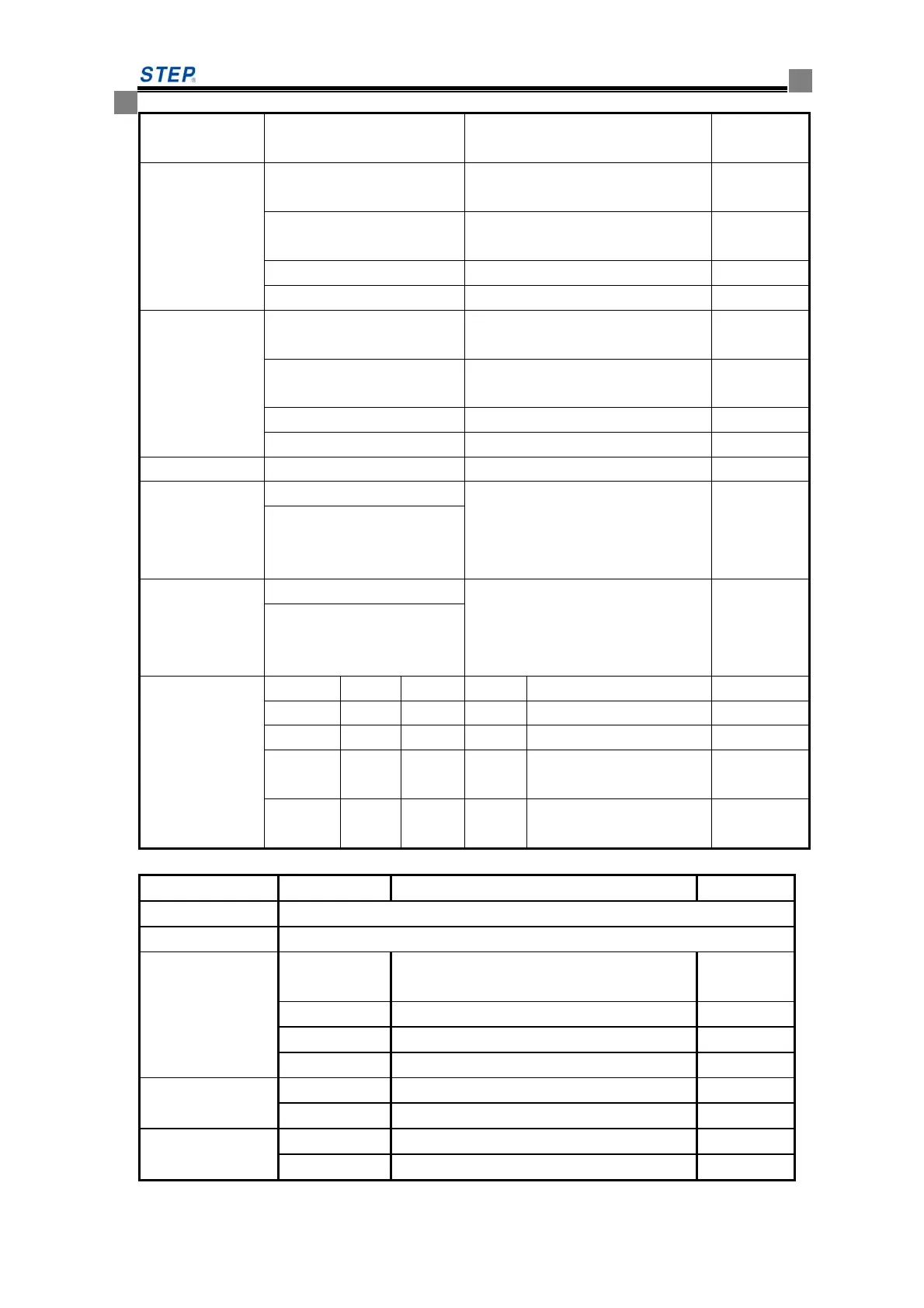
6 Input JP5.1-JP5.5 signal common
source
Default NO
JP6
1 Negative pole of power supply for
door-opening indicator light
2 positive pole of power supply for
door-opening indicator light
3 door-opening button ( GX5)
4 door-opening button
JP7
1 Negative pole of power supply for
door-closing indicator light
2 positive pole of power supply for
door-closing indicator light
3 door-closing button (GX6)
4 door closing button
DB1
program record burning slot
SW1
SW1.1 Simultaneously turn on, CAN
terminal resistor connected.
Simultaneously turn off, terminal
resistor disconnected.
SW1.2
SW2
SW2.1 Simultaneously turn on, program
record burning status;
simultaneously turn off, normal
running status.
SW2.2
SW3
SW3.1 SW3.2 SW3.3 SW3.4 operation cabinet type
ON OFF OFF OFF main operation cabinet
OFF ON OFF OFF rear operation cabinet
OFF OFF ON OFF the disabled operation
cabinet
OFF OFF OFF ON auxiliary operation
cabinet
Table 6.7 SM09IO/B I/O Port definition when used as car extension board
Socket No Terminal No Definition remark
JP1
Connecting car board SM.02/G
JP2
connecting the second car extension board
JP6
1 Output GY0 , door-opening holding
indicator light output
2 Output GY1,standby
3 Output GY2,standby
4 Output JP6.1-JP6.3 common port
JP7
1 Output GY3, standby
2 Output JP7.1 common port
JP8
1 Output GY4, standby
2 Output JP8.1 common port
 Loading...