Instruction Manual
for
AS380 Series Elevator Integrated Drive Controller
70
Chapter Five :Operator
AS 380 integrated drive controller is equipped with operator of LED indicator and 7-segment
code display. The programmable LED indicator in it can display the I/O condition and other basic
information of elevator. The 7-segment code can display the integrated unit parameter and fault
code. Besides, AS380 integrated drive controller can also support LCD handheld operator for the
elevator advanced adjustment.
5.1 The 7-segment display operator
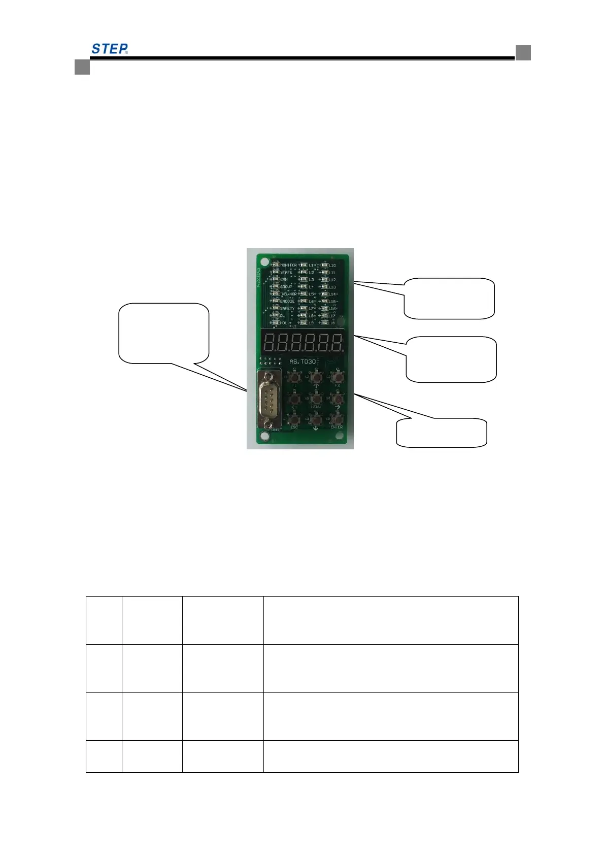
The appearance and definition of 7-segment display operator is as the below photo 5.1. The
detailed function explanation about the operation key is in table 5.2
Fig 5.1 7-segement operator
5.1.1 LED indicator light
7-segement display operator has 27 LED indicator light at the upper section, in which 9
indicator lights L19-L27 at the left side have fixed definition ( the corresponding meaning see
table 5.1, the 18 indicator lights L1-L18 in the middle are definable. See table 5.5
Table 5.1 L19-L27 definition explanation
Code
Nam
e
display definition remark
L19 MONITO
R
Community
monitor
communication
Flash—in communication
L20 STATE CPU in work Rapid
flash-normal/mid-speed-self-studying/low-speed-elevato
r fault/no flash-manufacturer contact
L21 CAN car/hoist way
communication
flash-in communication
LED indicator
light
7-segement
display
Function key
LCD handheld
operator port
 Loading...