Instruction Manual
for
AS380 Series Elevator Integrated Drive Controller
43
Peels off the insulation sleeve of bus at the very vicinity of terminal point, connects the
section unpeeled but not cut off at one end of the terminal and leave another end connected to
branches.
Bus Specification: bus length ≤500m;
Branch Length: ≤3m;
Terminal resistance: 120Ω terminal –matching resistance should be arranged at both ends of
the bus. (Note: without terminal-matching resistance, the anti-interference capacity of
communication may be impaired)
4.3.3Hoist way switch position
In elevator integrated drive controller system, hoist-way switch need to be arranged according to
the following two situations:
1. where the elevator speed is not more than 1.75m/s, it is required to install the two up and
down limit switch as well as two single-floor speed switch.
2. Where the elevator speed is more than 1.75m/s, not only the limit switches mentioned above
should be installed, but also up and down double floor forced slow car switch.
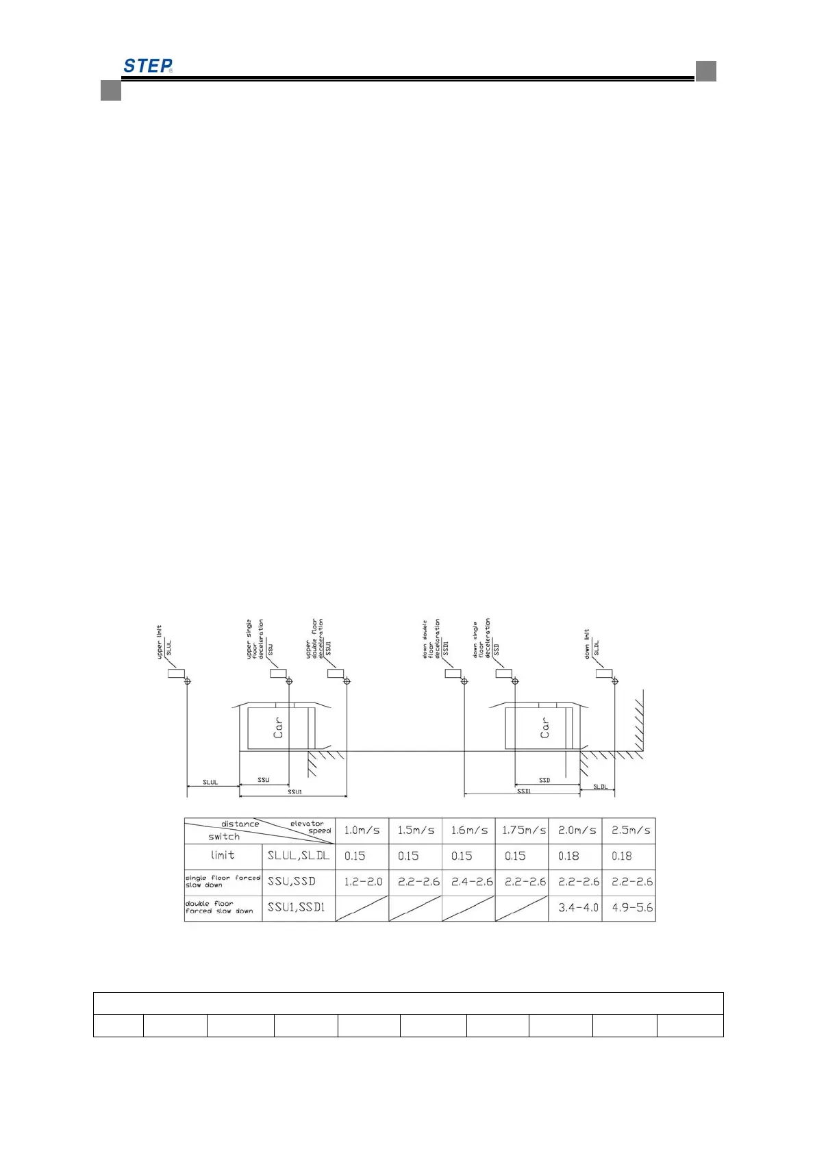
3. The detailed locations of hoist way switches see Figure 4.4 and table 4.1
Note: the switch locations vary based on the setting of deceleration slope. As a rule, the distance
for deceleration switch should always be set a little lower than the normal deceleration distance.
Figure 4.4 Detailed Locations of Shaft Switches
Table 4.1 installation clearance of deceleration switch in hoist way
Installation clearance of deceleration switch in hoist way
Rated 1.0m/s 1.5m/s 1.6m/s 1.75m/s 2.0m/s 2.5/ms 3.0m/s 3.5m/s 4.0m/s
 Loading...