Instruction Manual
for
AS380 Series Elevator Integrated Drive Controller
125
☆SM-04-VRJ plug-in specification and port definition
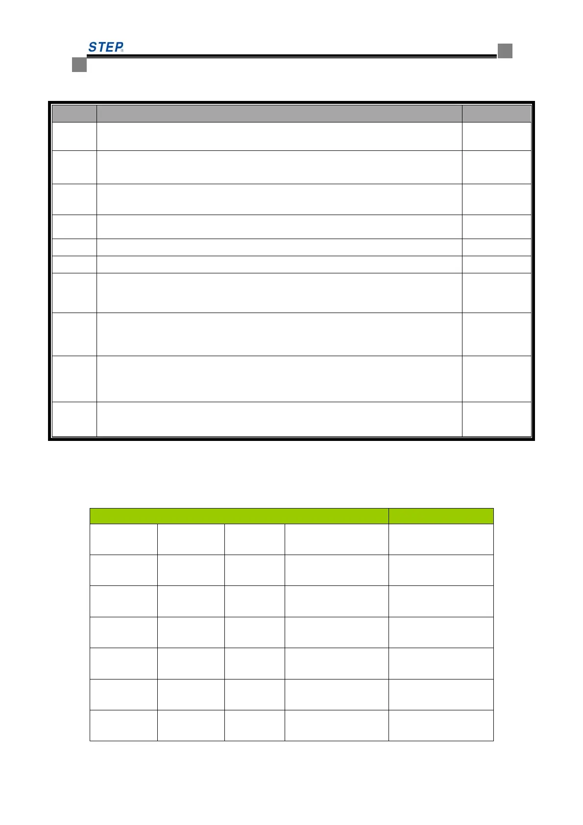
Table 6.18 SM-04-VRJ plug-in specification and port definition
Serial Descriptions Remarks
JP1
Serial port, of which Pin 1 for TXV+, Pin 2 for TXV-, Pin 3 for TXA+ and Pin 4 for
TXA- respectively.
CH3.96-4
JP2
Down-call terminals, of which Pin 1 -and Pin 2 + for button indicator, Pin 3 and Pin 4
for button input.
CH2510-4
JP3
Up-call terminals, of which Pin 1- and Pin 2+ for button indicator, Pin 3 and Pin 4 for
button input.
CH2510-4
JP4
Pin 3 and Pin 4 for the input of normal open contact of the lockout switch, Pin 1 and
Pin 2 for stand-by.
CH2510-4
JP5
standby CH2510-4
JP6
Program burning record slot/ RS232 communication port
S1
Set the address codes of the display Board with the jumper on, after that the jumper
MUST BE REMOVED.
S2
Bridge S2.1 and S2.2 to use JP2 as the button of three-wire system, otherwise, used as
button for four wire system.
S3
Bridge S3.1 and S3.2 to use JP3 as the button of three-wire system, otherwise, used as
button for four wire system
SW1
Resistor jumper of serial communication terminal, meanwhile shorting means the
connection of built-in 120Ω resistor.
6.5.9 Miscellaneous (A List of Display Codes)
A list of performance displays
Displays in Car No Voice Forecast
Inspection
Normal No
Special
symbol/otherwise
Re-leveling at
power off
Normal No
Special
symbol/otherwise
Independent
Normal No
Special
symbol/otherwise
Fireman
Normal No
Special
symbol/otherwise
Safety circuit
off
Normal No
Special
symbol/otherwise
Lockout
Normal No
Special
symbol/otherwise
Breakdown
Normal No
Special
symbol/otherwise
 Loading...