Instruction Manual
for
AS380 Series Elevator Integrated Drive Controller
127
B A B
Code 105 106 107 108 109 110 111 112 113 114 115 116 117 118 119
Display D1 D2 D3 D4 D 1F 2F 3F 4F 5F 1C 2C 3C 4C
Code 120 121 122 123 124 125 126 127 128 129 130 131 132 133 134
Display 1B 2B 3B 4B 1A 2A 4A CF LB E A UB LG UG 6A
Code 135 136 137 138 139 140 141 142 143 144 145 146 147 148 149
Display 6B 7A 7B 5B 6C SB 15A 13B K U S EG
Code 150 151 152 153 154 155 156 157 158 159 160 161 162 163 164
Display KG KE1 KE2 KE3 KE4 KE5 KE6 KE7 KE8 KE9 GF MZ SR 19
A
Z
Code 165 166 167 168 169 170 171 172 173 174 175 176 177 178 179
Display HP AB PH AA L1 L2 L3 PB -10 AG BE RF 1L 5L 1M
Code 180 181 182 183 184 185 186 187 188 189 190 191 192 193 194
Display 3M 4M B1
A
B2
A
B3
A
B4
A
PM 14
A
14
B
AS 15B 16
A
16
B
22
A
22B
Code 195 196 197 198 199 200 201 202 203 204 205 206 207 208 209
Display E1 E2 S1 S2 S3 E3 E4 49 50 51 52 53 54 55 56
Code 210 211 212 213 214 215 216 217 218 219 220 221 222 223 224
Display 57 58 59 60 61 62 63 64 P4 P5 LD JC S4 S5 SS
Code 225 226 227 228 229 230 231 232 233 234 235 236 237 238 239
Display LL 5C 9F LF UF FF 33
A
S6 S8 LP UP M
R
PC P6 P7
Code 240 241 242 243 244 245 246 247
Display P8 P9 P1
0
P3
A
P7
A
P8
A
P9
A
AF
The definitions and display symbols of the terminals may vary with the edition. The above
listing is the one based on the standard edition.
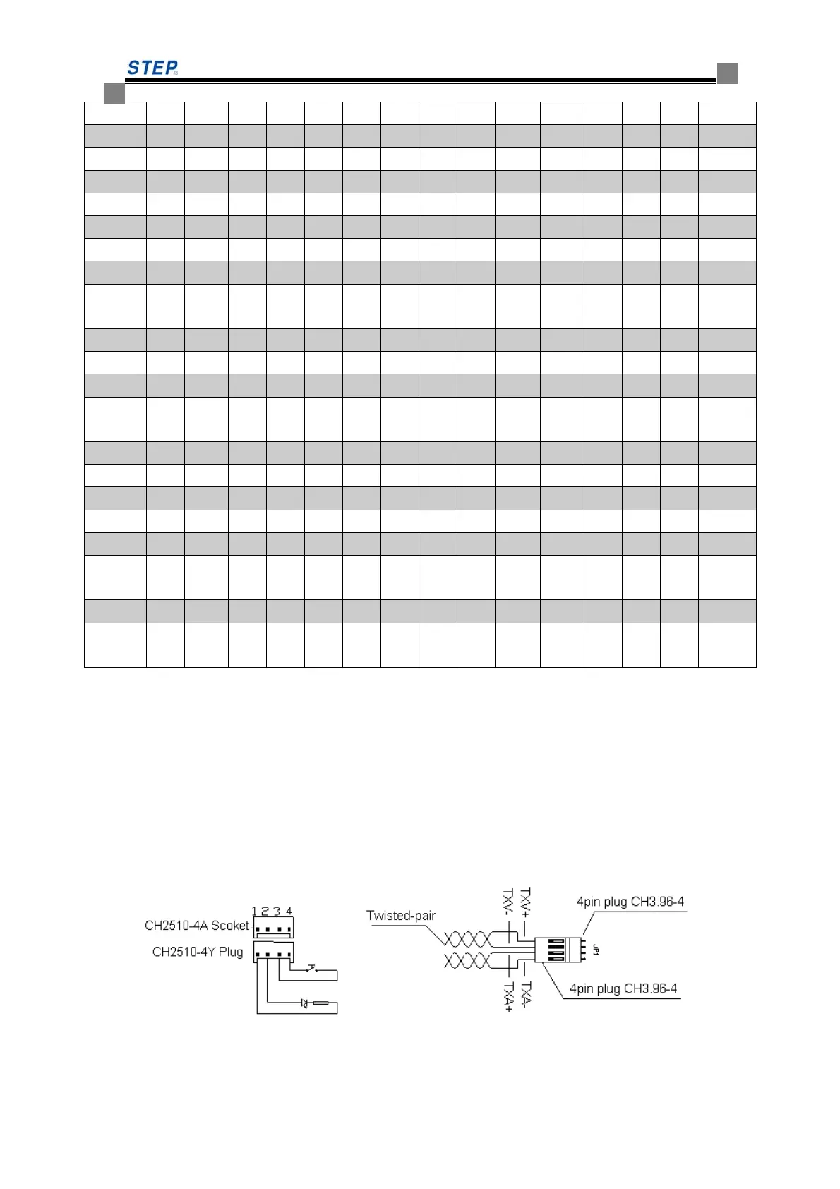
☆ Wiring and Connection
1. The connection of the display Board for power supply and communication is shown in Fig.
6.32, the power supply and communication is made available via a 4-pin plug, of which Pin 1
for TXV+, Pin 2 for TXV-, both with DC24V power supply; Pin3 for TXA+ and Pin 4 for
TXA- are communication lines. The lines for communication must be Twisted Pairs.
2 The connection between the display Board and the landing push button is shown in Fig. 6.31.
i.e., Pin 1 and Pin 2 for push-button indicator lamp, whereas Pin 3 and Pin 4 for the push button.
Fig. 6.31 Connection of the Push Button Fig. 6.32 Connection of Communication
Lines
 Loading...