Instruction Manual
for
AS380 Series Elevator Integrated Drive Controller
135
JP3-19 TXV1- Power supply negative terminal of elevator No.5 in the group control system
JP3-20 TXV1+ Power supply positive terminal of elevator No.5 in the group control system
Definition of power port of mainboard(supplied by switch power)
Pin Name Definition
JP4-1 0V negative terminal OV for +5V power supply
JP4-2 +5V +5Vpower supply
JP4-3 0V negative terminal OV for +24V power supply
JP4-4 +24V +24V power supply input
Definition of switching value input terminal (JP4 terminal)
Pin Name Definition
JP4-5 void
JP4-6 void
JP4-7 +24V input terminal insulated circuit
power supply positive
JP4-8 +24V input terminal insulated circuit
power supply positive
JP4-9 +24V input terminal insulated circuit
power supply positive
JP4-10 0V input terminal insulated circuit
power supply negative
JP4-11 0V input terminal insulated circuit
power supply negative
JP4-12 COM Common port of input terminal
form No.1 to No.8
JP4-13 Input terminal.8 Standby
JP4-14 Input terminal 7 Standby
JP4-15 Input terminal 6 check-in peak hour service switch
JP4-16 Input terminal 5 No 2 switch of service floor
switching scheme
JP4-17 Input terminal 4 No 1 switch of service floor
switching scheme
JP4-18 Input terminal 3 Check-off peak hour service
switch
JP4-19 Input terminal 2 Group partition switch
JP4-20 Input terminal 1 Abnormal power supply detection
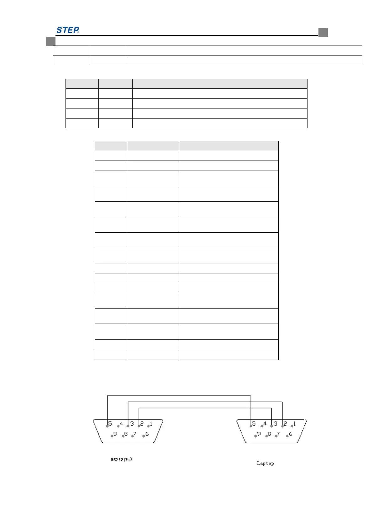
6.6.7.5 Description of other ports
P1: RS232, Monitor Port., for connection with the notebook PC..
 Loading...