PROPELLER UNIT HEATER
TABLE OF CONTENTS
2
DESCRIPTION
SPECIFICATIONS
Basic Description ....................................................
2
Performance & SpeciÞ cation Data ..........................4
SAFETY INFORMATION
Installation Codes ...............................................
2
, 3
Special Precautions ............................................
2
, 3
INSTALLATION
Locating Units .........................................................3
Proper Clearances ..........................................3, 5, 6
Combustion Air .......................................................6
Suspension of Units ............................................5, 6
Gas Supply Piping ..................................................7
Pipe Installation ......................................................8
VENTING .....................................................................9
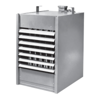
The gas unit heater is a factory assembled, low static
pressure type propeller fan heater designed to be
suspended within the space to be heated. THESE
HEATERS ARE NOT TO BE CONNECTED TO
DUCTWORK. The designs are certified by CSA
The following terms are used throughout this manual, in addition to CSA International requirements, to bring attention
to the presence of potential hazards or to important information concerning the product:
Indicates an imminently hazardous
situation which, if not avoided, may result in minor
injury or property damage.
NOTICE: Used to notify of special instructions on
installation, operation or maintenance which are
important to equipment but not related to personal
injury hazards.
International as providing a minimum of 80% thermal
efficiency, and approved for use in California when
equipped with spark ignition.
Do not alter these units
in any way.
If you have any questions after reading this
manual, contact the manufacturer.
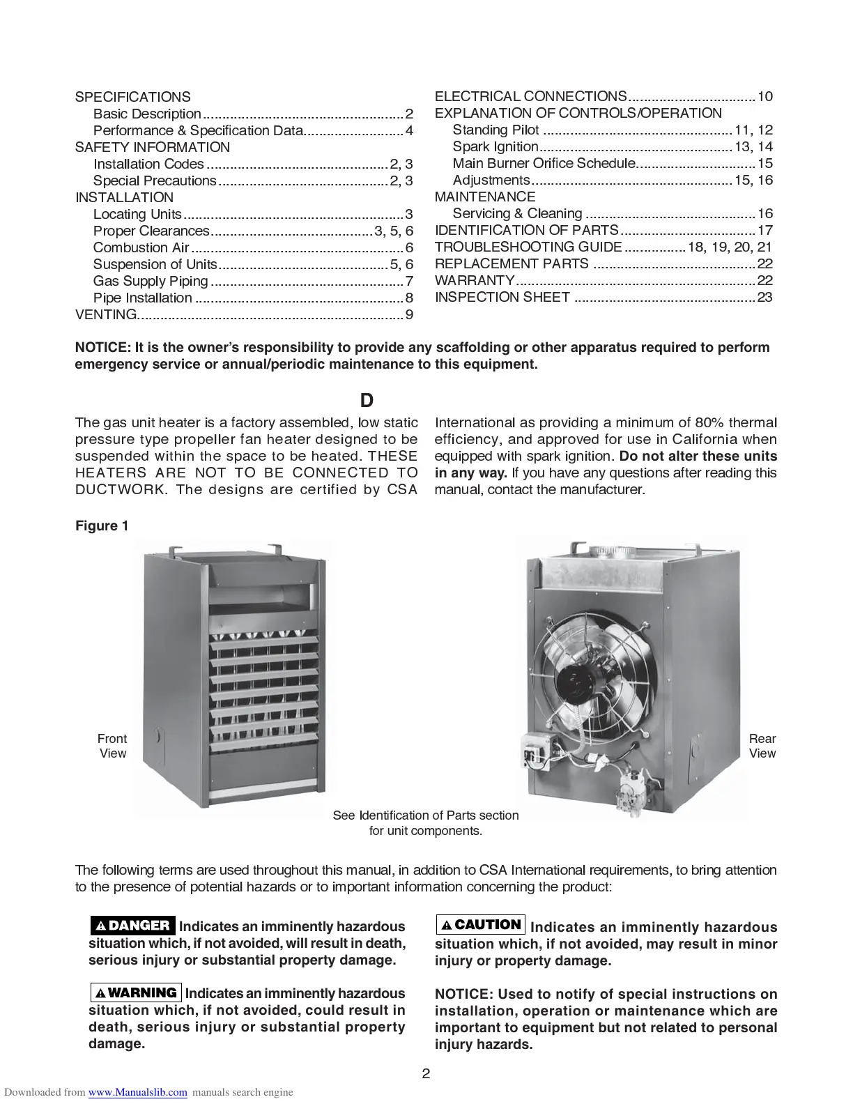
Figure 1
ELECTRICAL CONNECTIONS .................................
1
0
E
X
PLANATION OF CONTROLS
/
OPERATION
Standing Pilot .................................................
11
,
1
2
Spark Ignition ..................................................
1
3,
1
4
Main Burner OriÞ ce Schedule ...............................
1
5
Ad
j
ustments ....................................................
1
5,
1
6
MAINTENANCE
Servicing & Cleaning ............................................
1
6
IDENTIFICATION OF PARTS ...................................
1
7
TROUBLESHOOTING GUIDE ................
1
8,
1
9,
2
0,
2
1
REPLACEMENT PARTS ..........................................
22
WARRANTY ..............................................................
22
INSPECTION SHEET ...............................................
2
3
Indicates an imminently hazardous
situation which, if not avoided, will result in death,
serious injury or substantial property damage.
Indicates an imminently hazardous
situation which, if not avoided, could result in
death, serious injury or substantial property
damage.
NOTICE: It is the owner’s responsibility to provide any scaffolding or other apparatus required to perform
emergency service or annual/periodic maintenance to this equipment.
See IdentiÞ cation of Parts section
for unit components.
Front
View
Rear
View