5
INSTALLATION
Do not install unit heaters in
corrosive or fl ammable atmospheres! Premature
failure of, or severe damage to the unit will result!
Avoid locations where extreme
drafts can affect burner operation. Unit heaters
must not be installed in locations where air for
combustion would contain chlorinated, halo-
genated or acidic vapors. If located in such an
environment, premature failure of the unit will
occur!
When the unit is equipped with an automatic gas ignition
system, the unit heater must be installed such that the
gas ignition control system is not directly exposed to
water spray, rain or dripping water.
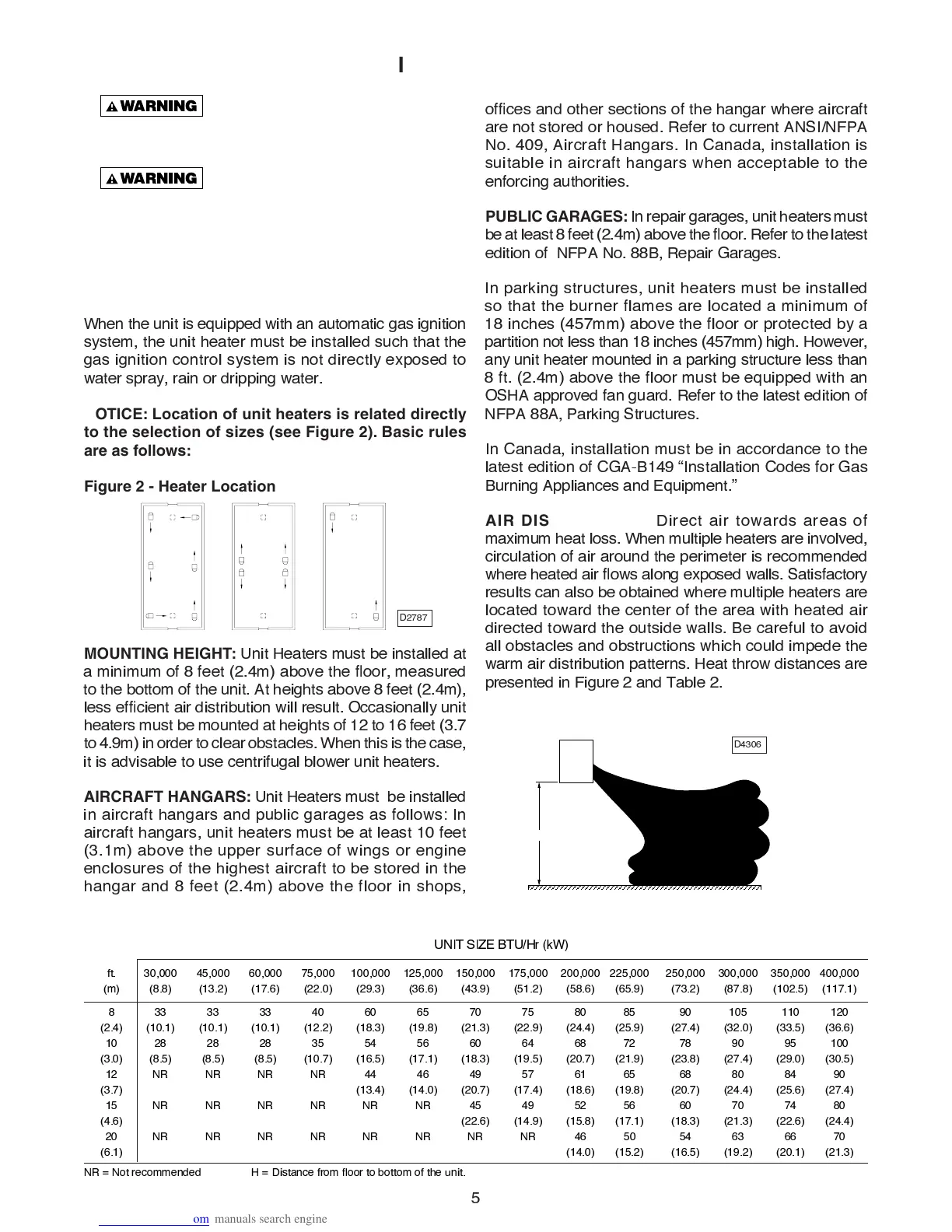
NOTICE: Location of unit heaters is related directly
to the selection of sizes (see Figure 2). Basic rules
are as follows:
Figure 2 - Heater Location
MOUNTING HEIGHT:
U
nit
H
eaters must be installed at
a minimum o
f
8
f
eet
(2
.
4
m
)
abo
v
e the
ß
oor, measured
to the bottom o
f
the unit.
A
t heights abo
v
e
8
f
eet
(2
.
4
m
)
,
less e
fÞ
cient air distribution will result.
O
ccasionally unit
heaters must be mounted at heights o
f
12
to
16
f
eet
(3
.
7
to
4
.
9
m
)
in order to clear obstacles. When this is the case,
it is ad
v
isable to use centri
f
ugal blower unit heaters.
AIRCRAFT HANGARS:
U
nit
H
eaters must be installed
in aircra
f
t hangars and public garages as
f
ollows
:
I
n
aircra
f
t hangars, unit heaters must be at least
1
0
f
eet
(3
.
1
m
)
abo
v
e the upper sur
f
ace o
f
wings or engine
enclosures o
f
the highest aircra
f
t to be stored in the
hangar and
8
f
eet
(2
.
4
m
)
abo
v
e the
f
loor in shops,
o
fÞ
ces and other sections o
f
the hangar where aircra
f
t
are not stored or housed.
R
e
f
er to current
A
NSI/NFP
A
N
o.
4
0
9
,
A
ircra
f
t
H
angars.
I
n
C
anada, installation is
suitable in aircra
f
t hangars when acceptable to the
en
f
orcing authorities.
PUBLIC GARAGES:
I
n repair garages, unit heaters must
be at least
8
f
eet
(2
.
4
m
)
abo
v
e the
ß
oor.
R
e
f
er to the latest
edition o
f
NFP
A
N
o.
88
B
,
R
epair
G
arages.
I
n par
k
ing structures, unit heaters must be installed
so that the burner
f
lames are located a minimum o
f
18
inches
(4
5
7
mm
)
abo
v
e the
f
loor or protected by a
partition not less than
18
inches
(4
5
7
mm
)
high.
H
owe
v
er,
any unit heater mounted in a par
k
ing structure less than
8
f
t.
(2
.
4
m
)
abo
v
e the
f
loor must be equipped with an
O
S
HA
appro
v
ed
f
an guard.
R
e
f
er to the latest edition o
f
NFP
A
88A
,
P
ar
k
ing
S
tructures.
I
n
C
anada, installation must be in accordance to the
latest edition o
f
C
G
A
-B
149
Ò
I
nstallation
C
odes
f
or
G
as
B
urning
A
ppliances and
E
quipment.
Ó
AIR DISTRIBUTION:
D
irect air towards areas o
f
maximum heat loss. When multiple heaters are in
v
ol
v
ed,
circulation o
f
air around the perimeter is recommended
where heated air
ß
ows along exposed walls.
S
atis
f
actory
results can also be obtained where multiple heaters are
located toward the center o
f
the area with heated air
directed toward the outside walls.
B
e care
f
ul to a
v
oid
all obstacles and obstructions which could impede the
warm air distribution patterns.
H
eat throw distances are
presented in
F
igure
2
and
T
able
2
.
Figure 2A - Heat Throw Distances
D
2787
“H”
D
43
0
6
f
t.
3
0
,
000
4
5,
000
6
0
,
000
7
5,
000
1
00
,
000
12
5,
000
1
5
0
,
000
17
5,
000
2
00
,
000
22
5,
000
2
5
0
,
000
3
00
,
000
3
5
0
,
000
4
00
,
000
(
m
)
(8
.
8)
(13
.
2)
(17
.
6)
(22
.
0
)
(29
.
3)
(36
.
6)
(43
.
9)
(
5
1
.
2)
(
5
8
.
6)
(6
5.
9)
(73
.
2)
(87
.
8)
(1
0
2
.5
)
(117
.
1)
8
33
33
33
4
0
6
0
6
5
7
0
7
5
8
0
8
5
9
0
1
0
5
11
0
12
0
(2
.
4)
(1
0
.
1)
(1
0
.
1)
(1
0
.
1)
(12
.
2)
(18
.
3)
(19
.
8)
(21
.
3)
(22
.
9)
(24
.
4)
(2
5.
9)
(27
.
4)
(32
.
0
)
(33
.5
)
(36
.
6)
1
0
28
28
28
3
5 5
4
5
6
6
0
64
68
72
78
9
0
9
5
1
00
(3
.
0
)
(8
.5
)
(8
.5
)
(8
.5
)
(1
0
.
7)
(16
.5
)
(17
.
1)
(18
.
3)
(19
.5
)
(2
0
.
7)
(21
.
9)
(23
.
8)
(27
.
4)
(29
.
0
)
(3
0
.5
)
12
NR
NR
NR
NR
44
46
49
5
7
61
6
5
68
8
0
84
9
0
(3
.
7)
(13
.
4)
(14
.
0
)
(2
0
.
7)
(17
.
4)
(18
.
6)
(19
.
8)
(2
0
.
7)
(24
.
4)
(2
5.
6)
(27
.
4)
1
5
NR
NR
NR
NR
NR
NR
4
5
49
5
2
5
6
6
0
7
0
74
8
0
(4
.
6)
(22
.
6)
(14
.
9)
(1
5.
8)
(17
.
1)
(18
.
3)
(21
.
3)
(22
.
6)
(24
.
4)
2
0
NR
NR
NR
NR
NR
NR
NR
NR
46
5
0
5
4
63
66
7
0
(6
.
1)
(14
.
0
)
(1
5.
2)
(16
.5
)
(19
.
2)
(2
0
.
1)
(21
.
3)
U
NI
T
SI
Z
E
B
T
U
/
H
r
(
k
W
)
“H”
NR
=
N
ot recommended
H
=
D
istance
f
rom
ß
oor to bottom o
f
the unit.
Table 2 - Standard Applications - Heat Throw Distances (Approximate) (see Figure 2A)
 Loading...