9
VENTING
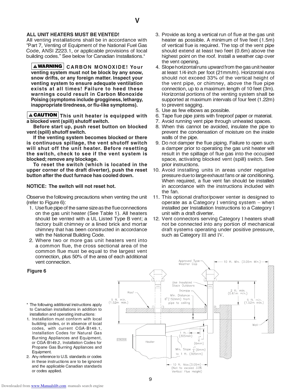
3. Provide as long a vertical run of ß ue at the gas unit
heater as possible. A minimum of five feet (1.5m)
of vertical ß ue is required. The top of the vent pipe
should extend at least two feet (0.6m) above the
highest point on the roof. Install a weather cap over
the vent opening.
4. Slope horizontal runs upward from the gas unit heater
at least 1/4-inch per foot (21mm/m). Horizontal runs
should not exceed 33% of the vertical height of
the vent pipe, or chimney, above the flue pipe
connection, up to a maximum length of 10 feet (3m).
Horizontal portions of the venting system shall be
supported at maximum intervals of four feet (1.22m)
to prevent sagging.
5. Use as few elbows as possible.
6. Tape ß ue pipe joints with Þ reproof paper or material.
7. Avoid running vent pipe through unheated spaces.
8. When this cannot be avoided, insulate the pipe to
prevent the condensation of moisture on the inside
walls of the pipe.
9
. Do not damper the ß ue piping. Failure to open such
a damper prior to operating the gas unit heater will
result in the spillage of flue gas into the occupied
space, activating blocked vent (spill) switch. See
prior instructions.
10. Avoid installing units in areas under negative
pressure due to large exhaust fans or air conditioning.
When required, a ß ue vent fan should be installed
in accordance with the instructions included with
the fan.
11. This optional draftor/power venter is designed to
operate as a Category
I
venting system
Ð
when
installed per Installation Instructions to a Category
I
unit with a draft diverter.
12.
V
ent connectors serving Category
I
heaters shall
not be connected into any portion of mechanical
draft systems operating under positive pressure,
such as Category
III
and
IV
.
ALL UNIT HEATERS MUST BE VENTED!
All venting installations shall be in accordance with
Ò
Part 7,
V
enting of
E
quipment of the
N
ational Fuel
G
as
Code, A
N
SI
Z
223.1, or applicable provisions of local
building codes.
Ó
See below for Canadian Installations.
*
CARBON MONOXIDE! Your
venting system must not be block by any snow,
snow drifts, or any foreign matter. Inspect your
venting system to ensure adequate ventilation
exists at all times! Failure to heed these
warnings could result in Carbon Monoxide
Poising (symptoms include grogginess, lethargy,
inappropriate tiredness, or fl u-like symptoms).
This unit heater is equipped with
a blocked vent (spill) shutoff switch.
Before start up, push reset button on blocked
vent (spill) shutoff switch.
If the venting system becomes blocked or there
is continuous spillage, the vent shutoff switch
will shut off the unit heater. Before resetting
the switch, check to see if the vent system is
blocked; remove any blockage.
To reset the switch (which is located in the
upper corner of the draft diverter), push the reset
button after the duct furnace has cooled down.
NOTICE: The switch will not reset hot.
O
bserve the following precautions when venting the unit
(refer to Figure 6)
:
1. Use ß ue pipe of the same size as the ß ue connections
on the gas unit heater (See Table 1). All heaters
should be vented with a U
L
L
isted Type
B
vent
;
a
factory built chimney or a lined brick and mortar
chimney that has been constructed in accordance
with the
N
ational
B
uilding Code.
2. Where two or more gas unit heaters vent into
a common flue, the cross sectional area of the
common flue must be equal to the largest vent
connection, plus 50% of the area of each additional
vent connection.
Figure 6
*
The following additional instructions apply
to Canadian installations in addition to
installation and operating instructions
:
1. Installation must conform with local
building codes, or in absence of local
codes, with current C
G
A-
B
14
9
.1,
Installation Codes for
N
atural
G
as
B
urning Appliances and
E
quipment,
or C
G
A-
B
14
9
.2, Installation Codes for
Propane
G
as
B
urning Appliances and
E
quipment.
2. Any reference to U.S. standards or codes
in these instructions are to be ignored
and the applicable Canadian standards
or codes applied.
 Loading...