27
09/24999842
Installation
SHE control panel TRZ Basic 4A/UP
Legend RBH/3A
Switch SHE Open
Switch SHE Closed
LED SHE Open
OK
LED operating OK
LED malfunction
Anschlussdose/Junction box
Motor
=
Motor
=
braun
brown
blau
blue
O3
O3
O3
O4
O4
O4
P
P
P
P1
P1
P1
S
S
S
S2
S2
S2
mehrere Lüftungstaster
Auf / Zu gemeinsam = Stop
several vent switches
open / closed together = Stop
mehrere Lüftungs-
taster mit Sicht-
anzeige LTA 25
several vent
switches with
visual display LTA 25
Mehrere Antriebe,
gesamte Stromaufnahme max. 4 A
several drives
total power consumption max. 4 A
1 2 3
8 10 11
8 9 10 11
letzter Antrieb
last drive
Lüftungstaster
Vent switch
Netz/
230 V/50Hz
Mains
Motor 24 V DC
max. 3 A
RWA-Bedienstelle/SHE man. call point
autom. Melder/ autom. detector
6
6
5
5
4
4
8
8
1
1
3
3
12 13 14 15 16 17
mehrere RWA-Bedienstellen RBH/3A
several SHE man. call points RBH/3A
mehrere autom.
Melder
several autom.
detectors
18 19
Leitungsüberwachung:
Überwachungsdioden in der letzten oder
einzigen Anschlussdose einklemmen.
Line monitoring: monitor diodes to connect
in the last or in the unique junction box.
Linienabschluss: in der letzten oder
einzigen RWA-Bedienstelle beiliegenden
Endwiderstand 10k (W) einklemmen.
Line termination: connect provided
10k end resistor (W) in the last or unique
SHE manual call point.
blau
blue
braun
brown
L N PE
1 2 3
8 9 10 11
12 13 14 15 16 17
18 19
Überwachung/
Monitoring
autom. Melder +
-autom. detector
Motor -
Motor +
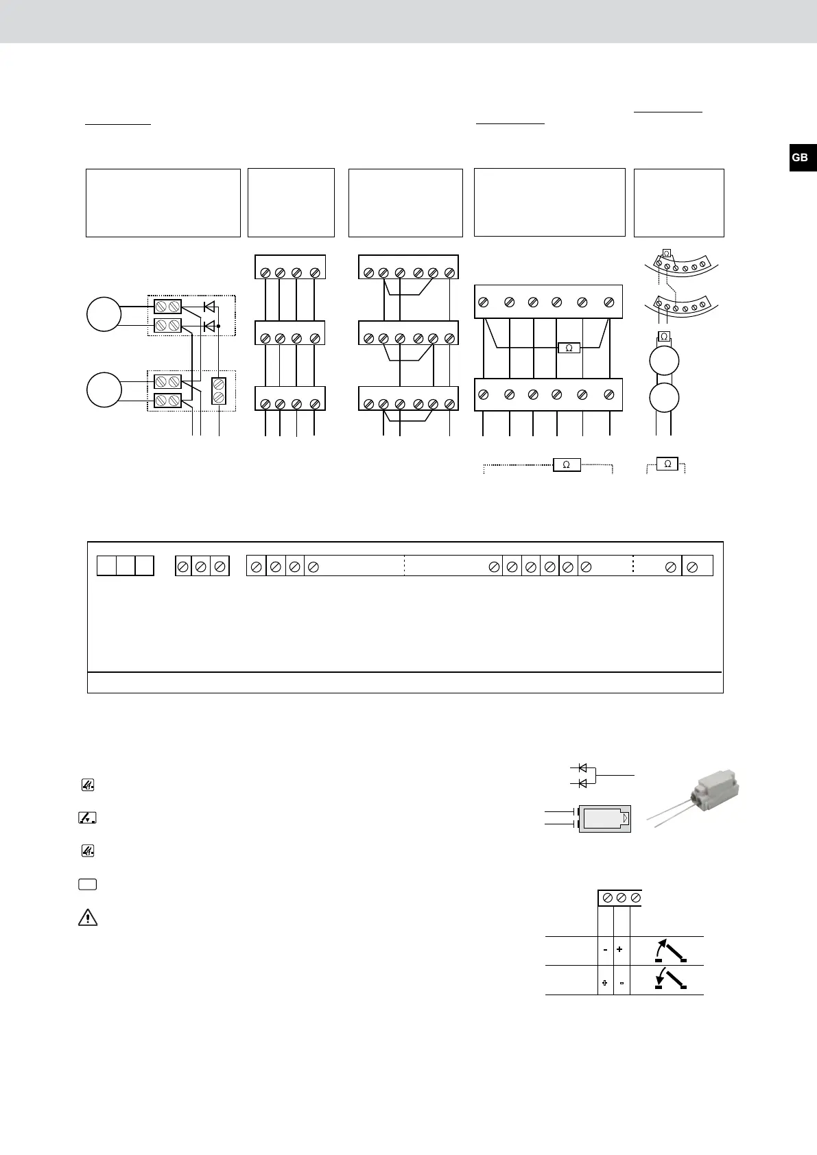
Anschlussklemmen in der Steuerzentrale
Terminals in the control panel
Keine RWA-Bedienstelle und/oder autom. Melder, Linienabschluss (W) in der Zentrale aufklemmen.
No SHE man. call point and/or autom. detector, connect line termination (W) in the control panel.
Netzleiter/
Neutralleiter/
Schutzleiter/
phase cond.
neutral cond.
PE conductor
Masse /
LED “Lüftung Auf”/
Taste ZU/
Taste AUF/
GND
LED “Vent open”
switch closed
switch open
L ro /ED t LED red
GND
LED gelb/LED yellow
D rLE g ün/ ED r nL g ee
Taste ZU/s switch clo ed
Taste AUF/s t h openwi c
1+
1+
5
5
2
2
4
4
AM/...
AM/...
1
2
3
4
5
6
letzter Melder
last detector
SSD...
UTD...
oder/
MSD...
or
19 18
+
1
2
3
4
5
6
1. Melder
1. detector
Linienabschluss: im letzten
oder einzigen autom. Melder
Endwiderstand 10k (W) ein-
klemmen.
Line termination: connect
provided 10k end resistor (W)
in the last or unique
automatic detector.
12 17 18 19
Line monitoring:
monitor diodes to connect in the last
or in the unique junction box.
several drives
total power consumption
max. 4 A
several vent
switches with
visual display
LTA 25
several vent switches
open / closed together
= Stop
Line termination: connect
provided 10k end resistor (Ω) in
the last or unique SHE manual
call point.
Line termination:
connect provided 10k
end resistor (Ω)
in the last or unique
automatic detector.
several SHE man. call
points RBH/3A
several autom.
detectors
Base USB...
1. detector
SSD...
UTD...
or
MSD...
Junction box
No SHE man. call point and/or autom. detector, connect line termination (Ω) in the control panel.
SHE man. call point
Autom. detector
Vent switch
Motor 24 V DC
max. 3 A
Mains
230 V / 50 Hz
Terminals in the control panel
Phase conductor
Motor -
GND
GND
Autom. detector +
Neutral conductor
PE conductor
Motor +
Monitoring
LED “Vent open”
Switch closed
Switch open
LED green
LED red
LED yellow
Switch closed
Switch open
Autom. detector -
Motor
=
Motor
=
last drive
brown
brown
blue
blue
last detector
Monitoring diodes
24 V DC
24 V DC
1 2 3
-
+
-
+
Polarity of the motor voltage for open/close
 Loading...