26
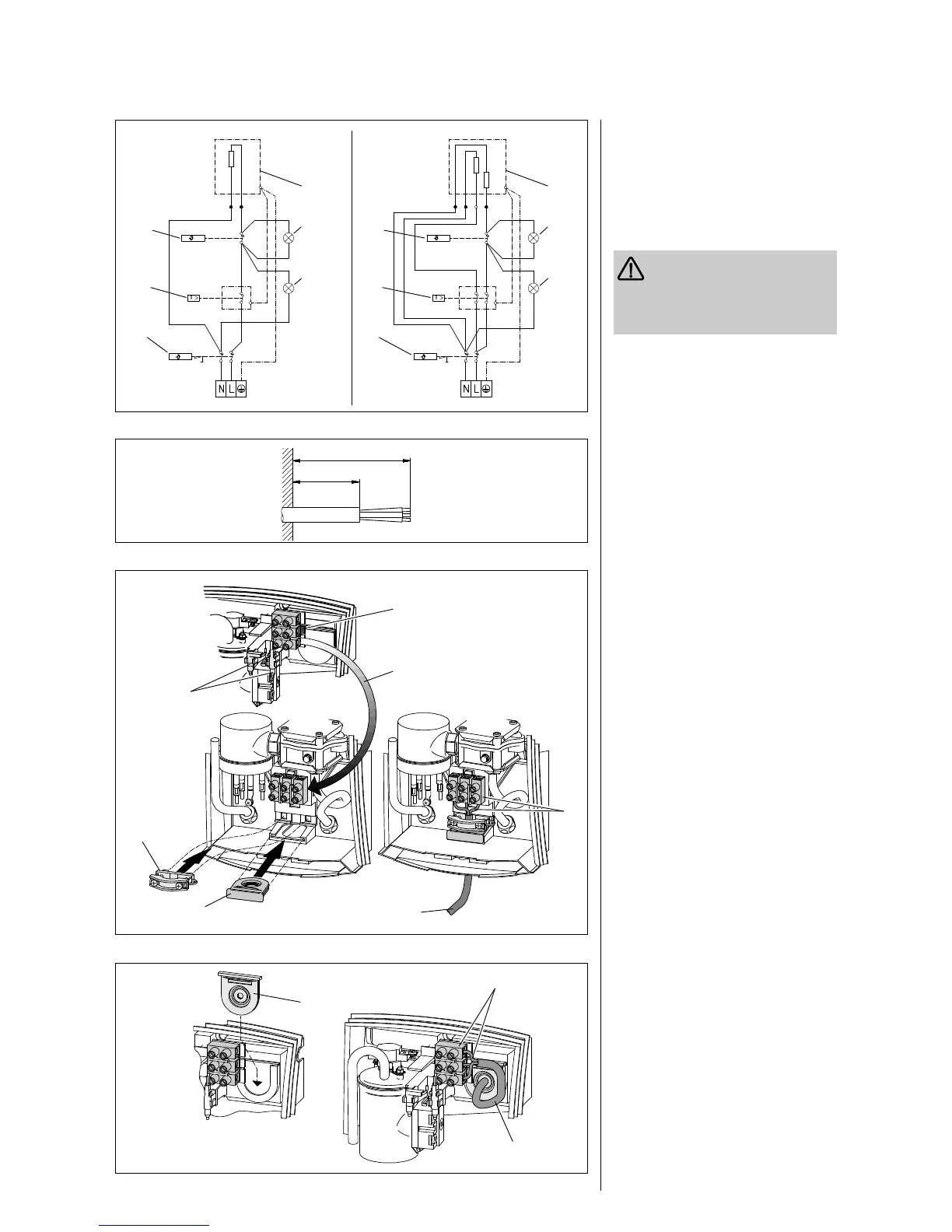
Electrical connection
Legend to Fig. 14
1 Heating element
2 “Overheating” monitor light
3 “Power” monitor light
4 Safety thermal cut-out
5 Differential pressure switch
6 Temperature monitor
To provide protection against the
penetration of water, the cable
seal (Fig. 16, Item 8, or Fig. 17, Item 14)
must be used. Cut out the sealing
diaphragm to fit the electric cable.
DHC 3 U (Fig. 16)
– Pass the connection cable provided
(Item 7) through the cable seal (Item 8)
and the strain relief collar (Item 9).
– Establish the electrical connection
(Item 10) in accordance with Fig. 14,
and tighten the screws of the strain
relief collar.
A protective earth contact socket is
required to connect the unit. After
concluding the installation (see page 9),
insert the mains plug.
DHC 6 U (Fig. 16):
– Push in the cable seal (Item 8)
– Establish the fixed-position lead (Item 7)
for the electrical connection (Item 10)
in accordance with Fig. 14
See page 27 for concluding the installation.
DHC 3, DHC 4, DHC 6, DHC 8:
– For concealed installation, the
connection lead must project with
insulation at least 65 mm out of the wall
(Fig. 15).
• Connection in the upper part of the
unit/surface installation or concealed
installation (Fig. 17).
– Slide in the cable seal (Item 14)
– Lay the fixed-location lead (Item 15) for
the electrical connection (Item 16) in
accordance with Fig. 14.
See page 27 for concluding the installation.
Alternative:
• Connection in the lower part of the
unit/surface installation
In the conditions as supplied, the unit is
prepared for electrical connection in the
upper part of the unit (terminal strip
upwards).
– Press the locking device of the terminal
strip (Item 12) downwards, draw the
strip out, and push it into the lower
area (Item 13).
Guide the connection leads sideways
between the differential pressure
switch and the rear wall.
– Slide in the cable seal (Item 8)
– Lay the fixed-location lead (Item 7) for
the electrical connection (Item 10) in
accordance with Fig. 14.
See page 27 for concluding the installation.
Fig. 16
7061.01
7059.01
Fig. 15
Fig. 14
7060.01
1/N/PE ~
220 ... 240 V
7058.01
Fig. 17
14
15
16
7
13
8
10
9 DHC ... U
DHC 3
DHC 3 U
DHC 4
DHC 6
DHC 6 U
DHC 8
1
2
3
4
5
6
1
2
3
4
5
6
115 mm
≥ 65 mm
1/N/PE ~
220 ... 240 V
11
12
 Loading...